
User Manual

Power Amplifier Serial I/F Spec.
9 Version 1.62
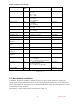
Fan
Fail
Flag
Clear
Amp
Online
Amplifier
Reset Flag
Clear
Reverse
Power
Shutdown
Flag Clear
Amplifier
Overdrive
Alarm
Flag Clear
Thermal
Alarm
Flag
Clear
Amplifier
Overdrive
Shutdown
Flag Clear
Thermal
Shutdown
Flag Clear
6 Reserved
7 Factory Communication
0Table 3-3
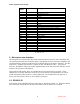
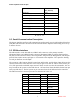
3.5 SPI Electrical Considerations
All signals are CMOS levels with 30%/70% thresholds. Devices driving the SPI bus must be
able to drive a load of 500 ohms // 2200pF with a rise-time of less than 1uS. The SN65176B
transceiver from TI is a recommended I/O device. It is differential, but can be used in a single-
ended mode.
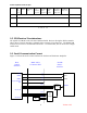
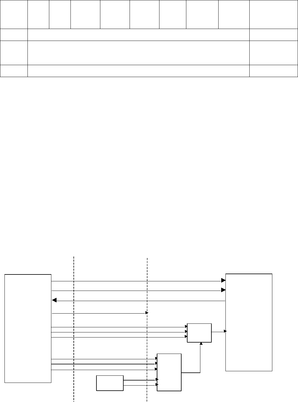
3.6 Serial Communication Format
Figure 3-1 below shows the connection between the host and the Power Amplifier:
CLK
MOSI
MISO
B+ (10-
15VDC
out)
A2,A1,A0
A5,A4,A3
SPIC
SPII
SPIO
SPISB
Backplane
ID
PA
Compare
Host
Control
Interface
DB15 SPI 1
Connector Shell
PA SPI
Device
Interface
Device
Select
2,3,4
5,6,7
8
9
10
11,12
14