
User Manual


Power Amplifier Serial I/F Spec.
8 Version 1.62
0Table 3-2
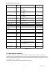
Note: Pins 11 and 12 will indicate to the amplifier its slot location in the rack.
Pin 11 Pin 12 Amplifier
Ground Ground 1
Ground Open 2
Open Ground 3
Open Open 4
Pins 13, 14, and 15 should be left open in the Sonik rack.
These pins will be used by the manufacturer for test purposes.
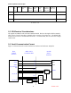
SPI bits A5-A3 are used to select the Power Amplifier module on the SPI BUS. SPI bits A2-A0
are used to select the register/device within the selected Power Amplifier module.
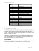
3.4 Power Amplifier Device ID
The Power Amplifier shall have SPI “devices” associated with SPI A2-A0 defined in Table 3-3:
Device
ID
Definition Device Size
(in bytes)
0 Temperature (read only)
Forward Power (read only)
Reflected Power (read only)
DC supply voltage (read only)
DC supply current (read only)
5
Status word (Read Only) For all bits except bit 6, the amplifier sets the bit
when the relevant condition occurs. The bit will stay set until cleared by a
write of a 1 to the corresponding bit in the control register. Bit 6 indicates
whether the amplifier is active or shut down. The amplifier may only be
brought online by writing a 1 to bit 6 of the control register, but shutdown
may occur either by writing a 0 to bit 6 of the control register, or by one of
the shutdown conditions being detected.
7 6 5 4 3 2 1 0
1
Fan
Fail
Flag
Amp
Online
Amplifier
Reset Flag
Reverse
Power
Shutdown
Flag
Amplifier
Overdrive
Alarm
Flag
Thermal
Alarm
Flag
Amplifier
Overdrive
Shutdown
Flag
Thermal
Shutdown
Flag
1
2 Phase Control (write only) 1
3 Attenuation Level (write only) 1
4 EEPROM (read/write) 4
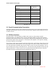
Control word (write only) 5
7 6 5 4 3 2 1 0
1