
User Manual


Power Amplifier Serial I/F Spec.
7 Version 1.62
0Table 3-1
3.2 Serial Communication Description
The Power Amplifier and host will communicate synchronously via a Serial Peripheral Interface
(SPI) Bus with the master located on the host and the Power Amplifier functioning as one of up
to 8 slave devices.
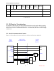
3.3 SPI Bus Interface
The SPI interface on the PA shall use a DB15 male connector as the primary interface
(designated SPI1), and a DB15 female connector (designated SPI2) as a daisy-chain interface.
All pins on both connectors will be wired in parallel. All pins will be RF bypassed, and all input
pins will have 10kO resistive pull-ups to +5V internal to the amplifier. The capacitive loading
on each pin shall not exceed 100pF.
The connector cable between the SPI control unit and first PA, and the daisy chain cables used to
connect between the 4 PAs will have wires only for pins 1-10. Pins 11 and 12 will be tied to pin
15 or left open inside each SPI1 input connector shell, in order to select the PA number. Pin 14
may be used for DC power to other SPI devices. No more than 25mA should be drawn from pin
14 by any SPI device. The DC power on pin 14 comes from the SCM board in the controller.
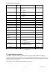
The SPI bus interface connector pin outs are described in Table 3-2:
Pin Description Pin Description
1 Shield GND 9 SPI MOSI
2 SPI A5 10 SPI MISO
3 SPI A4 11 Backplane ID0
4 SPI A3 12 Backplane ID1
5 SPI A2 13 Reset
6 SPI A1 14 +10-15VDC from
controller.
7 SPI A0 15 GND
8 SPI CLK
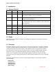
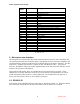
System Devices ID
(A5, A4, A3)
Reserved 0 0 0
Power Amplifier #1 0 0 1
Power Amplifier #2 0 1 0
Power Amplifier #3 0 1 1
Power Amplifier #4 1 0 0
Power Supply #1 1 0 1
Power Supply #2 1 1 0
Reserved 1 1 1