
User Manual


Power Amplifier Serial I/F Spec.
3 Version 1.62
1. Introduction
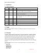
1.1 Version Control
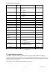
Date Author Revision Comment
12/20/00 Welte 1.00 Initial Revision
12/21/00 Welte 1.10 Added more clarity to section 2.4 and changed Figure 2-1 to
specify host as Master and size of transaction.
1/4/01 Welte 1.20 Redefined chip select, device ID mechanism. Made some
changes to timing diagrams.
1/9/01 Welte 1.30 Changes made in accordance to design review, namely remove
the –RackEnable signal, specify backplane values, make some
error corrections.
1/10/01 JS 1.40 Elaborated on hardware issues.
3/30/01 G. Nakao 1.41
6/6/01 G. Nakao 1.42 SPI Refinements
6/7/01 RMS 1.61 Further clarifications
9/12/01 J.Briggs 1.62 SPI Timing changes
1.2 Scope
This document is a technical description of the RF Power Amplifier Serial Peripheral Interface
(SPI) requirements.
1.3 Overview
The Power Amplifiers operate at approximately 133 watts average power, and will be combined
in parallel to achieve 400 watts average power, or 1200 watts peak power. Amplifier status and
configuration is done via the SPI interface. The amplifier section is comprised of 3 modules.
Two SPI interface connectors are to be located on the rear of each amplifier module. The SPI
interface is routed to each individual amplifier within the amplifier by daisy chain wiring.
In the event of an amplifier failure, the remaining amplifiers continue to operate, providing
continuous performance and soft fail operation. Failed amplifiers indicate their status via the SPI
interface.
The Power Amplifier must be capable of collecting and sending over the serial bus amplifier
status including:
temperature
forward power
reflected power
attenuator level
phase setting