
User Manual


Power Amplifier Serial I/F Spec.
10 Version 1.62
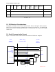
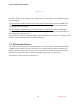
Figure 3-1
Note that the Host is the Master Device and therefore is the only device on the SPI bus to drive
the CLK signal.
The host changes its MOSI output on the falling edge of the SPI clock while the SPISB (chip
selected) is driven active low. The Power Amplifier is expected to sample data (SPII) on the
rising edge of the clock signal.
The host samples the MISO input on the rising edge of the SPI clock while the SPISB (chip
selected) is driven active low. The Power Amplifier is expected to change its output (SPIO) on
the falling edge of the SPI clock.
SPI transfers are variable length depending on the SPI device (refer to Table 3-3). During an SPI
transfer, data is transmitted and received simultaneously.
3.7 SPI Session Protocol
All SPI transfers are started and controlled by the host. A SPI transfer is started after the Power
Amplifier device address A5..A0 is selected and is complete when the address changes. The
address will always return to an inactive state (ie no SPI device within the system is selected).
SPI transfers in packets of 8 bits, with the most significant bit (bit 7) as the first bit.
The transfer waveform is shown in Figure 3-2: