
User's Manual
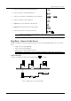
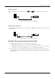
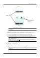
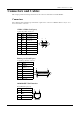
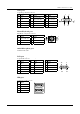
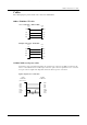
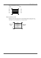
Table Of Contents
- Introduction
- Installation
- Specifications
- Connectors and Cables
- Troubleshooting

Winlinx - Hardware User’s Guide
Connectors and Cables 10
Connectors and Cables
This chapter provides detailed specifications for the Connectors and Cables used with Winlinx.
Connectors
The following tables and figures provide details of pins for the connectors of Winlinx. Refer to
Figure 2
for
the location of the connectors.
COM1 / COM2 (
Serial ports
)
9-pin D-Type Male Connector
Pin Signal Description
1 DCD Data Carrier Detect
2 RXD Receive Data
3 TXD Transmit Data
4 DTR Data Terminal Ready
5 GND Signal Ground
6 DSR Data Set Ready
7 RTS Request To Send
8 CTS Clear To Send
9 NC Not Connected
Printer port (
Parallel port
)
25-pin D-type Female connector.
Pin Signal
1STROBE
2 - 9 DATA 0 – 7
10 ACKNOWLEDGE
11 BUSY
12 PAPER END
15 ERROR
18 - 25 GROUND
10/100BASE-T LAN interface
RJ-45 Modular 8-pin jack
Pin Signal
1 TXD+
2 TXD-
3 RXD+
6 RXD-
1 5
6 9
13 1
25 14
1 8