
User's Manual
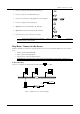
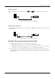
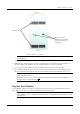
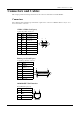
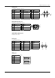
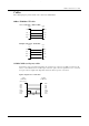
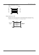
Table Of Contents
- Introduction
- Installation
- Specifications
- Connectors and Cables
- Troubleshooting

Winlinx - Hardware User’s Guide
Specifications 7
Figure 6: Base view of Winlinx
N
OTE
: P
LEASE RETAIN THE
N
YLON PLUG
;
IT WOULD BE REQUIRED IF YOU DECIDE TO MOVE THE UNIT
AT A LATER DATE
.
3.
Select the area on your desktop where you want to place Winlinx.
4.
Within this area, mark two points at a distance of 44mm. from each other. The two points should be in a
line that would be perpendicular to the sides of Winlinx when it is placed on the desktop.
5.
At each of the two points, drill a hole of 8mm. Diameter through the surface of your desktop.
6.
Place Winlinx such that the holes on the base panel are aligned with the holes on the desktop. Insert two
M6 screws through the aligned holes, from beneath the desktop and fasten them until the unit is secure.
N
OTE
: A
FTER MOUNTING THE UNIT TO THE DESKTOP
,
ENSURE THAT THE CONNECTIONS ON THE REAR
PANEL ARE FIRMLY IN PLACE
.
N
OTE
: F
OR SECURITY
,
YOU CAN LOCK
W
INLINX TO THE TABLE OR DESKTOP USING A
K
ENSINGTON
LOCK PROVIDED ON THE REAR PANEL
.
Step Six: Start Winlinx
To start Winlinx, switch the external power supply ON and press the power-on switch provided on the front
panel. Refer to the
Software User Manual
for instructions to setup the software.
N
OTE
: E
VEN IF
W
INLINX IS SWITCHED OFF
,
AN AUXILIARY
5V DC
POWER SUPPLY IS AVAILABLE ON
THE MOTHER
-
BOARD
. T
O COMPLETELY STOP POWER SUPPLY
,
THE EXTERNAL POWER SUPPLY HAS TO BE
SWITCHED OFF
.
Front
Rear
Rubber
p
ads
Holes for securing
Winlinx to the desk (the
hole on the left has the
nylon plug)