Winlinx Thin Client Family TC 4000 Series Hardware User’s Guide VXL Instruments Ltd.
Winlinx - Hardware User’s Guide Copyright and Trademark notices Copyright © 2000 VXL Instruments Limited. ALL RIGHTS RESERVED. Information in this document is subject to change without notice and does not represent a commitment on the part of the manufacturer. No part of this manual may be reproduced or transmitted in any form or means, electronic or mechanical, including photocopying and recording, for any purpose, without the express written permission of the manufacturer.
Winlinx - Hardware User’s Guide Federal Communication Commission (FCC) statement FCC Certification awaited. Warnings Preface • Only equipment certified to comply with Class B (computer input/output devices, terminals, printers etc.) should be attached to this equipment, and they must have shielded interface cables. • Any changes or modifications not expressly approved by the party responsible for compliance could void the user's authority to operate this equipment.
Winlinx - Hardware User’s Guide Preface Thank you for purchasing the Winlinx Thin Client Terminal. This manual contains information to setup and use the hardware of Winlinx. The manual consists of the following chapters: • Introduction: provides an overview of Winlinx. • Installation: contains the procedure to setup the hardware. • Specifications: provides hardware, mechanical, electrical, interface and operating environment specifications.
Winlinx - Hardware User’s Guide Table of Contents INTRODUCTION ........................................................................................................................................... 1 Overview.........................................................................................................................................................................1 Standard Features .............................................................................................................
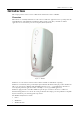
Winlinx - Hardware User’s Guide Introduction This chapter provides a brief overview of Thin Clients and lists the features of Winlinx. Overview Thin Clients are essentially terminal devices that connect to multi-user application servers operating under the Citrix MetaFrame, Citrix WinFrame and Windows NT operating system. They communicate with the application server via the ICA3 protocol developed by Citrix Systems Inc.
Winlinx - Hardware User’s Guide Standard Features • 200MHz National Geode GXLV processor • 32MB SO-DIMM memory (expandable to 128MB) • 100% ICA3 protocol compliant • High-speed windows performance • Secure access to network resources. • Low administration costs. • Support for high resolutions (up to 1280x1024) and 256 colors. • 10/100 Base-T Ethernet port • Dual high-speed serial ports and a parallel port.
Winlinx - Hardware User’s Guide Installation This chapter describes the procedure to install the hardware of Winlinx. Step One: Unpack The carton in which Winlinx was shipped to you contains the following: • Winlinx • Power Adapter • Power Cord • Mouse • CD containing manuals NOTE: PLEASE RETAIN THE ORIGINAL CARTON AND PACKING MATERIAL. THEY WOULD BE REQUIRED TO AVOID DAMAGE DURING TRANSIT (IF REQUIRED IN FUTURE). Step Two: Prepare the site 1.
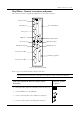
Winlinx - Hardware User’s Guide Step Three: Connect accessories and power The connectors for devices supported by Winlinx are located on the rear panel. DC power inlet Network port PC-card/LCD slot Video port USB ports Kensington Lock Microphone input Stereo line out PS/2 Mouse port PS/2 Keyboard port Serial port (COM1) Parallel port (printer) Serial port (COM2) Figure 2: Rear panel of Winlinx Refer to page 10 for details about the connectors and cables.
Winlinx - Hardware User’s Guide 9 Connect your keyboard to the PS/2 Keyboard port 9 Connect your mouse to the PS/2 Mouse port 9 Connect your serial devices (E.g Modem) to the COM ports 9 Connect your printer to the parallel port 9 Optional: Connect the LCD unit to the LCD port 9 Optional: Insert the PC-Card into the PC-Card slot 9 Connect the AC power cord to the power inlet.
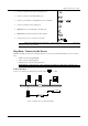
Winlinx - Hardware User’s Guide Direct connection 1 or Connect an RS232 cross cable from a serial port server. 2 - of Winlinx to a serial port of the Winlinx Thin Client COM PORT Server COM PORT RS232C CROSS Figure 4: Direct Connection through RS232 Dial-in remote connection Connect an RS232 straight cable from one of the serial ports of Winlinx to a modem that is in turn connected to a telephone line.
Winlinx - Hardware User’s Guide Front Rubber pads Holes for securing Winlinx to the desk (the hole on the left has the nylon plug) Rear Figure 6: Base view of Winlinx NOTE: PLEASE RETAIN THE NYLON PLUG; IT WOULD BE REQUIRED IF YOU DECIDE TO MOVE THE UNIT AT A LATER DATE. 3. Select the area on your desktop where you want to place Winlinx. 4. Within this area, mark two points at a distance of 44mm. from each other.
Winlinx - Hardware User’s Guide Specifications This chapter contains hardware, mechanical, electrical, interface and operating environment specifications for Winlinx. Hardware • Processor: National Geode GXLV 200MHz • VGA Memory: Unified Video Memory, up to 4MB display RAM • Flash: 8MB / 16MB / 32MB on board flash • RAM: 32MB, expandable to 128MB • Power Management: VESA display power management • Internal Smart Card reader (optional) Mechanical • Height: 256 mm. • Width: 86 mm.
Winlinx - Hardware User’s Guide External Interfaces • COM1/COM2 serial ports: • 10Base-T/100Base-TX port: 10/100 Mbps LAN interface • Printer port (parallel): ECP/EPP compatible, 25-pin D-type female • Mouse port: PS/2 compatible • Keyboard port: PS/2 compatible • Video Port: SVGA compatible, supporting 1280x1024, 1024x768, 800x600 and 640x480 resolutions, 256 colors • Stereo output port: SB-16 compatible stereo sound • Microphone port: Mono phone jack • USB ports: USB devices • L
Winlinx - Hardware User’s Guide Connectors and Cables This chapter provides detailed specifications for the Connectors and Cables used with Winlinx. Connectors The following tables and figures provide details of pins for the connectors of Winlinx. Refer to Figure 2 for the location of the connectors.
Winlinx - Hardware User’s Guide Video port 15-pin D-type Female Connector Pin Signal Pin Signal Pin Signal 1 Red 6 Red return GND 11 No Connection 2 Green 7 Green return GND 12 No Connection 3 Blue 8 Blue return GND 13 Horizontal Sync 4 No Connection 9 No Connection 14 Vertical Sync 5 GND 10 No Connection 15 No Connection 5 1 10 6 15 11 Mouse/Keyboard port PS/2 Mouse / Keyboard connector Pin Signal Pin Signal 1 Mouse / KBD data 4 VCC 2 NC 5 Mouse / KBD C
Winlinx - Hardware User’s Guide Cables The following figures provide details of the cables used with Winlinx. 10Base-T/100Base-TX cable Cross Connection - (Without Hub) RJ45 Pin RJ45 Pin TXD+ 1 3 RXD+ TXD- 2 6 RXD- RXD+ 3 1 TXD+ RXD- 2 TXD- 6 Straight Connection - (With Hub) RJ45 Pin RJ45 Pin TXD+ 1 1 TXD+ TXD- 2 TXD- 2 RXD+ 3 3 RXD+ RXD- 6 RXD- 6 COM1/COM2 (serial ports) cables Serial devices such as modems and printers use 25-pin D-type connectors for RS232 connections.
Winlinx - Hardware User’s Guide 9-pin to 25-pin Straight Connection 9 Pin Connector (Thin Client) RTS DTR TXD GND DCD RXD DSR CTS 25 Pin Connector 7 4 3 5 1 2 6 8 4 20 2 7 8 3 6 5 RTS DTR TXD GND DCD RXD DSR CTS Printer (parallel port) cable This figure provides details of pin-connections of the Standard Centronics parallel cable. Some manufacturers have changed pin-functions or polarity on their printers. For such printers, custom cables may be necessary. For details, refer to your printer manual.
Winlinx - Hardware User’s Guide Troubleshooting This chapter contains solutions for problems you may encounter while using Winlinx. If a problem persists even after you implement the solutions provided here, or if you encounter a problem not listed here, please contact your nearest VXL Service Center or email support@vxl.net. For more information on the product and for a list of authorized service centers please visit us on the web at www.vxl.net.