Thin Client Hardware Installation Guide Copyright Notice © 1988 VXL Instruments Limited. ALL RIGHTS RESERVED, Document Number : 600010103038 Z00 1st Edition, October’ 98 Printed in INDIA information io this document is. subject to change without notice and does not represent a commitment on the part of VXL Instruments Limited. The software, which includes.
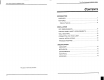
Thin Client Hardware Installation Guide This page is intentionally let blank “thin Client Hardware installation Guide CONTENTS 0 INTRODUCTION OVERVIEW... FEATURES PHONE! FERTILIZES sss 8 INSTALLATION SITE REQUIREMENTS .. PRECAUTIONS & SAFETY REQUIREMENTS 8 WALL MOUNTING... CONNECTING THE THIN CLIENT. TYPICAL INSTALLATIONS TROUBLE SHOOTING 14 SPECIFICATIONS MECHANICAL coon Ernie sis asn sec: 18 ENVIRONMENTAL Loon eiirieasimnens sparseness ELECTRICAL ovens INTERFACE ..
Thin Client Hardware Installation Guide CONNECTORS & CABLING INFORMATION CONNECTORS COMMODORE Printer Port (Parallel) 10/100BASE-T LAN Interface. VEO POR iri Mouse / Keyboard Port Audio / Micro Prone Port... eerie 19 CABLING REQUIREMENTS. 10/100BASE-T Cabling... COMICAL (Serial Port) Cabling . Printer Cabling...
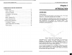
Thin Client Hardware Installation Guide FEATURES The Willing Pro Thin Client terminal: « utilizes an industry standard 200MHz Cyril Mediated MMX high speed processor with 16MB DIM memory {expandable to 128MB} + is 100% ICA 3 protocol compliant. + offers high speed windows performance. « provides secure access to network resources. « provides extremely low administration costs. « supports high resolution up to 1280x1024, 256 colors. « has a 10/100Base-T Ethernet port.
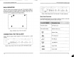
Thin Client Hardware Installation Guide WALL MOUNTING The Thin Client can be mounted on the wall. This provision helps in cabling of the network and better utilization of space. When the unit is to be wall mounted, the rubber bush on the bottom side has to be removed, shown as dotted fine in the figure below. Figure 2 Bosom View of the Thin Client CONNECTING THE THIN CLIENT Ensure that the power switch located on the front panel is in OFF position.
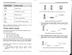
Thin Client Hardware Installation Guide Parallel Printer 16 Bit Stereo line output Microphone input 5 S S-Video output (optional) “Thin Client Hardware Installation Guide nL Frost 3 workstation Thar sis & Vv Composite Video output (optional) Refer to "Appendix-B, Connectors & Cabling Information” for more details about the connectors and cables. TYPICAL INSTALLATIONS The Thin Client communicates with the Win Frame application server using the ICA 3 protocol.
Thin Client Hardware installation Guide TROUBLE SHOOTING The following is a fist of general problems and their solutions. 1) When switched on, Power LED does not glow + Ensure that the power cord is properly plugged. « Ensure that the fuse in the plug, if fitted, is working. 2) Power LED glows but no display « Check whether the monitor video cable is properly plugged. 3) Mouse { or Keyboard ) is not working + Check whether the mouse {or keyboard) connector is properly plugged.
EE Thin Client Hardware Installation Guide ELECTRICAL Line Voltage 100 Vio 240 V AC (+8, -10 %) Line Frequency 50/60 Hz Power 58 W max Power Inlet 3A, 3 pin power socket (IEC 320) Power Outlet 2A, 3 pin power socket INTERFACE COMMODORE Serial Ports + RS232C compatible operating at 115.
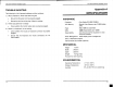
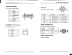
— | Thin Client Hardware Installation Guide Thin Client Hardware Installation Guide 5 1 Printer Port (Parallel) 4A A Video Port 25 Pin D-type Female connector. QO ens QO 15 Pin D-type Female Connector 104 avs >: Pin Signal vv 1 STROBE DATA-7 A A Pin | Signal Pin | Signal Pin | Sigma! 10 ACKNOWLEDGE off GND 11_| No Connection 1 BUSY VDODOBOLOLOD 1 {Red 6 | Red return io Cot 2 | Green 7} Green return GND 12 No Connection 2 PAPER END v 18 ERROR Blue 8 | Blue rectum GND 13 _| Horizontal Sync 18.
Thin Client Hardware Installation Guide CABLING REQUIREMENTS 10/100BASE-T Cabling Cross Connection (Without Hub) Ras AE Fin fin x0 1] [sax TD 2 5 RXD. RAD+ 2 1 Teds AD: 6 2 Straight Connection (With Hub) R445 aes Pin Pin x01 1] PRS To 2 2 TXDBXDs 3 3 RX RXD§ © RXD20 Thin Client Hardware Installation Guide COMMODORE (Serial Port) Cabling Serial devices like modems and printers use 25 pin D-type connector for R232 connections.
22 Thin Client Hardware Installation Guide Printer Cabling The table below gives the pin connections of the Standard Electronics para lie! cable. Since some manufacturers have changed pin functions or polarity on their printers, custom cables may be necessary. Refer to your printer manual for interfacing details. } gh Strobe rr 2.