CT-100C SERIES SIX-SLOT VXIBUS CHASSIS USER’S MANUAL P/N: 82-0102-000 Released November 16, 2007 VXI Technology, Inc.
VXI Technology, Inc.
www.vxitech.com TABLE OF CONTENTS INTRODUCTION Table of Contents......................................................................................................................................................3 Certification .........................................................................................................................................................4 Warranty .....................................................................................................................
VXI Technology, Inc. CERTIFICATION VXI Technology, Inc. (VTI) certifies that this product met its published specifications at the time of shipment from the factory. VTI further certifies that its calibration measurements are traceable to the United States National Institute of Standards and Technology (formerly National Bureau of Standards), to the extent allowed by that organization’s calibration facility, and to the calibration facilities of other International Standards Organization members.
www.vxitech.com DECLARATION OF CONFORMITY Declaration of Conformity According to ISO/IEC Guide 22 and EN 45014 MANUFACTURER’S NAME VXI Technology, Inc. MANUFACTURER’S ADDRESS 2031 Main Street Irvine, California 92614-6509 PRODUCT NAME Six-Slot VXIbus Chassis MODEL NUMBER(S) CT-100C PRODUCT OPTIONS All PRODUCT CONFIGURATIONS All VXI Technology, Inc.
VXI Technology, Inc. GENERAL SAFETY INSTRUCTIONS Review the following safety precautions to avoid bodily injury and/or damage to the product. These precautions must be observed during all phases of operation or service of this product. Failure to comply with these precautions, or with specific warnings elsewhere in this manual, violates safety standards of design, manufacture, and intended use of the product. Service should only be performed by qualified personnel.
www.vxitech.com WARNINGS (CONT.) Avoid Electric Shock To avoid electric shock or fire hazard, do not operate this product with the covers removed. Do not connect or disconnect any cable, probes, test leads, etc. while they are connected to a voltage source. Remove all power and unplug unit before performing any service. Service should only be performed by qualified personnel. Ground the Product This product is grounded through the grounding conductor of the power cord.
VXI Technology, Inc. SUPPORT RESOURCES Support resources for this product are available on the Internet and at VXI Technology customer support centers. VXI Technology World Headquarters VXI Technology, Inc. 2031 Main Street Irvine, CA 92614-6509 Phone: (949) 955-1894 Fax: (949) 955-3041 VXI Technology Cleveland Instrument Division VXI Technology, Inc.
www.vxitech.
www.vxitech.com SECTION 1 INTRODUCTION INTRODUCTION The CT-100C portable C-size VXIbus mainframe provides cost-effective test situations in a small footprint. When using VMIP™ instruments such as DMMs, waveform generators, digitizers, etc., complete test scenarios can easily be configured.
VXI Technology, Inc. GENERAL DESCRIPTION The CT-100C chassis is a portable, C-size, six-slot, VXIbus compatible chassis that conforms fully to VXIbus Specification Revision 2.0. The chassis employs a multi-layer backplane to ensure premium VXIbus and VMEbus performance and provides all power supplies required by the VXIbus specification. The CT-100C supports conventional existing rack designs through an optional rackmounting kit (see Section 1).
www.vxitech.com FLEXIBILITY The CT-100C is designed to provide flexibility of use in bench-top and rackmount applications, as well as in portable environments. The outside cover is removable for easy access to the VXIbus modules during bench-top development, troubleshooting, or calibration. For rackmount applications, a rackmount kit allows the CT-100C to mount flush or be recessed four inches.
VXI Technology, Inc. CT-100C MAINFRAME FEATURES FRONT PANEL FEATURES POWER SWITCH Feature 1 When elevated, the mainframe is in standby mode, where power is supplied to the mainframe, but not to the VXI modules. When depressed, power is supplied to both mainframe and VXI modules VOLTAGE INDICATORS Feature 2 Indicates whether specific backplane voltages are within specifications. See Figure 1-4 for details. FAN INDICATOR Feature 3 Indicates whether the fan voltages are within specifications.
www.vxitech.com VOLTAGE MONITOR LEDS The power supply lines are monitored and displayed on the front panel, providing information pertaining to the chassis operational status. Power Voltage Monitors +5V +12V +24V +5V Stby -5.
VXI Technology, Inc. TABLE 1-1: J201 CONNECTOR PIN ASSIGNMENTS Pin Number 1 2 3 4 5 6 7 8 9 10 11 12 13 14 15 16 17 18 19 20 21 22 23 24 25 NOTE Description +5 V Monitor† -12 V Monitor† -24 V Monitor† -2 V Monitor† Remote Power Switch +5 V Output‡ +12 V Output‡ +5 V Standby Input Ground Backplane Reset I/O N/C N/C Fan OK Output +12 V Monitor† +24 V Monitor† -5.2 V Monitor† Ground Remote Power Switch Return Ground Ground +5 V Standby Ground AC Fail I/O Ground N/C Monitor lines function as outputs only.
www.vxitech.com CT-100C SPECIFICATIONS GENERAL SPECIFICATIONS SIZE 6.96" (176.78 mm) W x 15.00" (381.00 mm) H x 21.3" D (541.02 mm) Six C-size VXIbus card slots (see Figure 1-6 for details) WEIGHT 22 lb / 10 kg VXIBUS VERSION 2.0 MTBF 100,000 hr MTTR 5 min ENVIRONMENTAL SPECIFICATIONS OPERATING LOCATION This chassis should be operated indoors in a controlled environment, protected from exposure to the elements (i.e. direct sunlight, precipitation, wind, etc.). Pollution degree 2. Installation Category II.
VXI Technology, Inc. POWER SPECIFICATIONS USEABLE POWER 500 W to 50 °C, derated by 2.5%/ °C above 50 °C DC SUPPLY VOLTAGE Voltage +5 V -5.2 V -2 V +12 V -12 V +24 V -24 V POWER INPUT Input Voltage / Freq. Nominal AC Inrush Current Input Power Input Leakage Input Harmonics Fuse POWER SUPPLIES Peak Current (IMP) 40 A 10 A 8A 8A 4A 4A 4A Dynamic Current (IMD) 5A 5A 2A 2A 2A 2A 2A Allowed Variation +0.25 V / -0.125 V -0.26 V / +0.125 V -0.10 V / +0.72 V +0.60 V / -0.36 V -0.60 V / +0.36 V +1.20 V / -0.
www.vxitech.com 3.0 Pressure Drop - mm H2O 2.5 2.0 Fa na 1.5 Fan 1.0 0.5 tH igh Sp e ed at L ow Spe ed 0.0 0 2.0 4.0 6.0 Airflow - liters/s 8.0 10.
VXI Technology, Inc. 21.000 (533.40) 8.100 (205.74) P ower Voltage M onitors +5 V + 12 V + 2 4V +5 V S t b y - 5 .2 V -12 V -2 4V -2 V FA N 16.425 (417.20) 14.979 (380.47) 0 1 2 3 4 5 CT-100C VXI Mainframe Note: Dimensions in parentheses are in millimeters. 0.343 (8.71) VXI Technology ! WARNING - TO PREVENT POSSIBLE ELECTRIC SHOCK HAZARD, DISCONNECT POWER CORD BEFORE REMOVING THE POWER SUPPLY MODULE FROM THE MAINFRAME.
www.vxitech.com SECTION 2 INSTALLATION INTRODUCTION When the CT-100C is unpacked from its shipping carton, the contents should include the following items: (1) CT-100C Six-Slot Chassis (1) CT-100C Module User’s Manual (this manual) (1) Power cord All components should be immediately inspected for damage upon receipt of the unit.
VXI Technology, Inc. REMOTE POWER-ON OPTION If the CT-100C mainframe is to be installed in a remote location, it is possible to apply and remove power from the unit via the remote power pins located on connector J201. To utilize the remote power feature, set the front panel switch to the standby position. Remove the power cord, then remove the power supply from the chassis and place the jumper on the power interface board to the 2 – 3 position (see Figure 2-1 for power supply removal instructions).
www.vxitech.com +5 V STANDBY USAGE To prevent timers and other circuits from loosing power when the CT-100C is in standby mode, +5 V Standby pins are made available on connector J201. An external power source can be wired to these pins with a maximum allowed current of 1 A total across Pins 8 and 21, as these pins are wired in parallel.
VXI Technology, Inc. FAN SPEED SWITCH A fan speed selector switch is located at the rear of the CT-100C chassis. To set the fans to operate at HIGH speed, move the switch at the rear of the chassis to the left. At HIGH speed, the chassis is provided maximum cooling to the instruments. The fans will operate in the LOW speed mode when the fan speed switch is toggled to the right. The low speed mode provides for quieter operation, but decreases the cooling capability of the fans.
www.vxitech.com RACKMOUNT OPTION INSTALLATION OVERVIEW This section contains the procedures for installing a CT-100C chassis in a standard 19” relay rack. The available rackmounting options are: Option 52 – Rackmount Ear Kit Option 53 – Rackmount Door Kit Option 57 – 20” Slide Kit Option 58 – 24” Slide Kit The rackmount ear kit provides the basic hardware necessary to rackmount the CT-100C chassis.
VXI Technology, Inc. RACKMOUNT KIT INSTALLATION The rackmount kit (Option 59) provides the basic hardware necessary to rack mount the CT-100C chassis. With the chassis being only 15” wide, standard rack support rails cannot provide mechanical support to the chassis. If the equipment mounted below the CT-100C cannot provide mechanical support to the chassis, either 20” or 24” rack slides will be required to support the chassis when installed into the rack.
www.vxitech.
VXI Technology, Inc. RACK SLIDE INSTALLATION (20” AND 24”) The 20” and 24” slide hardware kits (Options 63 and 64, respectively) provide standard flanges to mount the slides into standard EIA relay racks. It should be noted that the slide flanges in the front should be installed behind the rack’s front panel mounting rails. This will allow the rackmounting ears to sit flush with the front of the rack.
www.vxitech.com 5. Locate the slide hardware kit provided. Install the rack flanges to the slides as required by the application using the hardware in the kit. Note that the screws are inserted from the inside of the slides and the nuts would show on the outside. 6. Install the slides to the mounting brackets already installed on the chassis using the provided hardware.
VXI Technology, Inc. RACKMOUNT DOOR KIT INSTALLATION The rackmount door kit (Option 60) provides the necessary hardware to install a 1/8” thick aluminum door in front of the rackmounted chassis. This option requires that the rackmount ear kit also be installed and configured for recessed mounting. The door may be customer modified to hold connectors, controls, indicators and similar components. Required Tools 1. 2. 3.
www.vxitech.
VXI Technology, Inc. ACRYLIC RACKMOUNT DOOR KIT INSTALLATION An acrylic rackmount door is offered as an alternative to the aluminum rackmount door. The kit (Option 65) provides the necessary hardware to install a 1/8” thick acrylic door in front of the rackmounted chassis. An installation diagram is provided on the following page for ease of assembly. This option requires that the rackmount ear kit also be installed and configured for recessed mounting. Required Tools 1. 2. 3.
www.vxitech.com 7. Install the door by its hinges to the rackmount ear using four 3/8” black pan head screws provided with the option kit. 8. Test that the door opens and closes smoothly and adjust the latch as necessary to secure the door when latched close.
VXI Technology, Inc. INSTALLATION OF VXI MODULES OVERVIEW After the successful installation of rackmount accessories, the chassis is ready for installation of the VXIbus base units (i.e. an SMP1100, SMP1200, etc.). It is recommended that the instruments be installed after rackmount accessories have been installed to avoid any unnecessary physical strains that may be incurred during the installation of the accessories. Whether single- or doublewide, the process of installation is simple. Required Tools 1.
www.vxitech.com DISCONNECTING THE MAINFRAME To disconnect the CT-100C from its installation, simply follow the instructions below: 1. Place the mainframe in standby by depressing the power switch. 2. Remove the power cord from the mainframe to ensure that no power is running to the mainframe. 3. Remove all cabling associated with the VXI modules installed in the CT-100C. 4. If the chassis is rack mounted, remove the chassis from the rack by removing the screws that attach the mainframe to the rack.
VXI Technology, Inc.
www.vxitech.com SECTION 3 SERVICE INFORMATION INTRODUCTION There are no operating instructions required for the CT-100C VXIbus chassis. After the chassis is installed, operation is completely transparent to the operator. Just plug in the instruments then power up the chassis. NOTE Service should only be performed by qualified personnel. Le service devrait seulement être assure par le personnel qualifié. REPLICABLE PARTS LIST The following table lists the parts that can be replaced on the CT-100C chassis.
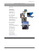
VXI Technology, Inc. CT-100C POWER SUPPLY REPLACEMENT The CT-100C should operate without the need for service. In the event that the cooling fans or power supply must be replaced, they are contained in a single, easy to remove module. Replacement of the power supply can be accomplished as follows: 1. Remove the AC power cord from the chassis. To avoid the possibility of shock, wait a minimum of ten seconds for electricity to dissipate from the mainframe after removing power.
www.vxitech.
VXI Technology, Inc. CLEANING THE MAINFRAME During normal operation, dust is likely to accumulate inside the power supply of the CT-100C. To remove this dust, power down the chassis and remove the power cord. Follow the instructions provided on the previous page to remove the power supply from the mainframe. After removing the power supply, use a pressurized air can to remove any dust present.
www.vxitech.com INDEX Numerics V 5V STANDBY ...............................................................................12 usage.........................................................................................23 voltage ............................................................................................ 18 VXIbus ........................................................................................... 12 A W airflow ................................................................