
Specifications

– 5 –
STOCK POT INSTALLATION, OPERATION, SERVICE & PARTS
The gas inlet is located at the rear and lower left side
of the range. To ensure maximum operating efficiency,
the range must be connected with a gas supply line as
large or larger ID (net inside diameter) than the
3
⁄4" gas
pipe inlet provided on the range.
Pipe gas supply to the range. Make sure the pipes
are clean and free of obstructions, dirt, and piping
compound.
Codes require that a gas shutoff valve be installed in
the gas line ahead of the range. Be sure the gas shutoff
valve is accessible in the final installed location.
All ranges are equipped with fixed orifices for use with
natural or propane gas and no adjustment is necessary.
Standard orifices are set at 5" W.C. (Water Column) for
natural gas supply, and 10" W.C. (Water Column) for
propane gas supply. No further adjustment should be
required.
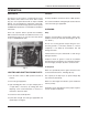
A gas pressure regulator is supplied with the range and
must be installed on the manifold pipe at the rear of the
range when the range is connected to the gas supply.
The arrow on the regulator shows direction of gas flow.
CAUTION: Installing the pressure regulator with the
gas flow in the wrong direction could damage the
pressure regulator.
NOTE: If the proper gas pressure regulator is not
installed, it will void the warranty.
A leak limiter is supplied with every regulator to allow
excess gas pressure to escape. Do not obstruct the leak
limiter on the gas pressure regulator as obstruction may
cause the regulator to malfunction.
WARNING: PRIOR TO LIGHTING, CHECK ALL
JOINTS IN THE GAS SUPPLY LINE FOR LEAKS.
USE SOAP AND WATER SOLUTION. DO NOT USE
AN OPEN FLAME.
After piping has been checked for leaks, all piping
receiving gas should be fully purged to remove air.
TESTING THE GAS SUPPLY SYSTEM
When test pressures exceed
1
⁄2 psig (3.45 k Pa), the
range and its individual shutoff valve must be discon-
nected from the gas supply piping system.
When test pressure are
1
⁄2 psig (3.45 k Pa) or less, the
range must be isolated from the gas supply system by
closing its individual manual shutoff valve.
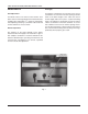
LEVELING THE RANGE
Once gas connections have been made, position the
range in its final installation location. Place a carpenters
level on the top grate and turn the adjustable feet to
level the range from side-to-side and front-to-back.
VENT
The range should be located under a ventilation
hood. Construction and installation of ventilating hoods
must comply with local codes and with National Fire
Protection Association Standard #96, “Vapor Removal
from Cooking Equipment” (latest edition), available from
the National Fire Protection Association, Battery March
Park, Quincy, MA 02269.
Adequate air should be provided in the kitchen to
replace air taken out by the ventilating system.