SERVICE MANUAL VPX SERIES ELECTRIC COUNTERTOP STEAMERS MODEL ML VPX3 126586 VPX5 126588 - NOTICE This Manual is prepared for the use of trained Vulcan Service Technicians and should not be used by those not properly qualified. If you have attended a Vulcan Service School for this product, you may be qualified to perform all the procedures described in this manual. This manual is not intended to be all encompassing.
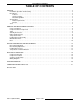
VPX SERIES STEAMERS TABLE OF CONTENTS GENERAL . . . . . . . . . . . . . . . . . . . . . . . . . . . . . . . . . . . . . . . . . . . . . . . . . . . . . . . . . . . . . . . . . . . . . . . . . . . . . . . . Installation, Operation and Cleaning . . . . . . . . . . . . . . . . . . . . . . . . . . . . . . . . . . . . . . . . . . . . . . . . . . . . . . . . Introduction . . . . . . . . . . . . . . . . . . . . . . . . . . . . . . . . . . . . . . . . . . . . . . . . . . . . . . . . . . . . . . . . . . . . . . . .
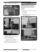
VPX SERIES STEAMERS - GENERAL GENERAL INSTALLATION, OPERATION AND CLEANING Hardness of 2-3 grains (34-35ppm) Total dissolved solids (TDS) less than 60ppm Ph factor of 7.0 to 7.5 These specifications can easily be obtained with the use of a properly maintained water softener. Refer to the Installation & Operation Manual for specific instructions. NOTE: Daily cleaning is required. INTRODUCTION 2.
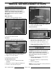
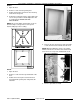
VPX SERIES STEAMERS - REMOVAL AND REPLACEMENT OF PARTS REMOVAL AND REPLACEMENT OF PARTS COVERS AND PANELS WARNING: DISCONNECT THE ELECTRICAL POWER TO THE MACHINE AT THE MAIN CIRCUIT BOX. PLACE A TAG ON THE CIRCUIT BOX INDICATING THE CIRCUIT IS BEING SERVICED. Right Side Panel 1. Remove screws from bottom of panel. 4. Pull the combination left side and rear panel off. 5. Reverse procedure to install. Lower Front Cover 1. Remove screws from the lower front cover. 2. Slide panel down to clear top cover. 3.
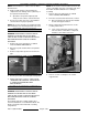
VPX SERIES STEAMERS - REMOVAL AND REPLACEMENT OF PARTS 4. Reverse procedure to install replacement component and check steamer for proper operation. NOTE: If replacing temperature control, see "TEMPERATURE CONTROL CALIBRATION ADJUSTMENT FOR ELEVATION" in "SERVICE PROCEDURES AND ADJUSTMENTS". 3. Grasp thermostat body and push up to slide holding tabs out from mounting bracket. 4. Apply a small amount of "thermal transfer compound" to the mating surface (disk side) of the replacement thermostat.
VPX SERIES STEAMERS - REMOVAL AND REPLACEMENT OF PARTS NOTE: Thermostat base is a brass 5/8" hex with a threaded stem. 4. Apply a small amount of "thermal transfer compound" to the mating surface (disk side) of the replacement thermostat. A. Spread the compound completely and evenly over the surface of the thermostat. NOTE: As the steamer is disassembled, remove the sheets of insulation from top, rear and left side, and the bottom. Retain insulation for use during reassembly. 1.
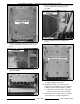
VPX SERIES STEAMERS - REMOVAL AND REPLACEMENT OF PARTS 7. Disconnect high limit thermostat lead wires and remove high limit from heating element assembly. 8. Remove heating element assembly from steamer. 5. Remove mounting nuts & washers from the rear cooking compartment support legs and remove base. 6. Disconnect heating element lead wires from element terminals. 9. Clean Loctite residue from heating element assembly mounting stud threads. 10. Apply approximately 4 oz.
VPX SERIES STEAMERS - REMOVAL AND REPLACEMENT OF PARTS A. Temporarily install a flat washer and nut on all mounting studs. Hand tighten only. A. Place wooden blocks opposite door handle to level and support steamer. 3. Grasp component panel and remove screws securing it to the base. B. Tighten each nut to 100 in-lb using the sequence as shown. A. Lower component panel and leave at side of steamer so that all the component lead wires can remain connected. 4.
VPX SERIES STEAMERS - REMOVAL AND REPLACEMENT OF PARTS 5. Remove mounting nuts & washers from the rear cooking compartment support legs and remove base. DOOR WARNING: DISCONNECT THE ELECTRICAL POWER TO THE MACHINE AT THE MAIN CIRCUIT BOX. PLACE A TAG ON THE CIRCUIT BOX INDICATING THE CIRCUIT IS BEING SERVICED. Removal 1. Remove top cover as outlined under "COVERS AND PANELS". 2. Open the door. 3. Pull hinge rod up. 4. Reverse procedure to install, making sure the door bushings are in place. 6.
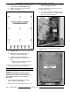
VPX SERIES STEAMERS - REMOVAL AND REPLACEMENT OF PARTS Gasket 1. Open the door. 2. Remove screws from the gasket plate. 3. Pull the gasket plate out from the door housing and remove the gasket. 4. Position the new gasket on the gasket plate and reverse the procedure to install. Adjust the door as outlined under "DOOR SEALING ADJUSTMENT". NOTE: Do not over tighten gasket plate screws as this will compress the gasket excessively and interfere with proper door sealing. 4.
VPX SERIES STEAMER - SERVICE PROCEDURES AND ADJUSTMENTS Latch Assembly 1. Open the door. 2. Remove screws from the top and bottom of the door. 3. Pull the "inner" door panel out from the door housing with the gasket plate and gasket still attached. 4. Remove the screws from the side edge of the door that secure the latch mechanism and remove the latch from the door. NOTE: When installing, the latch lever must rest on top of the handle latch screw. 5. Reverse procedure to install.
VPX SERIES STEAMER - SERVICE PROCEDURES AND ADJUSTMENTS 6. If necessary, tighten all screws an additional ½ turn and repeat step 5. To adjust: 1. Reinstall the striker with the slot pointing upwards and "hand tighten" nut only. 2. Close the door to center the striker in the oval mounting hole. 7. Repeat step 6 until the door closes properly and no steam "leaks" are seen around the gasket seal. HEATING ELEMENT TEST 3. Open the door and check the strikers’ slot for horizontal alignment.
VPX SERIES STEAMER - SERVICE PROCEDURES AND ADJUSTMENTS VOLTAGE KW PER ELEMENT AMPS PER ELEMENT 1 PH 3 PH OHMS PER ELEMENT ELEVATION (FT) TEMPERATURE (°F) 208 3 14.4 8.3 14.4 Sea Level 210 240 3 12.5 7.2 19.2 1,000 208 480 3 3.6 76.8 2,000 206 208 5 24.0 14.0 8.70 3,000 204 240 5 21.0 12.0 11.5 4,000 202 480 5 6.0 46.0 5,000 200 6,000 198 7,000 196 8,000 195 9,000 or above 194 NOTES: 1. Values in the table are nominal. Tolerance is +5/-10%. 2.
VPX SERIES STEAMER - ELECTRICAL OPERATION ELECTRICAL OPERATION COMPONENT FUNCTION Buzzer . . . . . . . . . . . . . . . . . . Signals end of a "cook" cycle when cooking time expires. Contactor . . . . . . . . . . . . . . . Supplies line voltage to heating element assembly. Relay R1 . . . . . . . . . . . . . . . . Supplies power to temperature control. Transformer . . . . . . . . . . . . . Provides 240V to the control circuit (480V only). Heater Light (green) . . . . . . Indicates steamer is heating.
VPX SERIES STEAMER - ELECTRICAL OPERATION 2) SEQUENCE OF OPERATION a. Wiring diagram 7264 will be used to explain the electrical sequence of operation. Timed Cooking Mode 1. A. Steamer connected to correct voltage and is properly grounded. B. Cooking mode switch (power) off. C. High limit thermostat closed. D. Standby thermostat closed. E. Temperature control is setup properly and is ready to use. F. Door closed (door switch closed). G. Timer "off". H.
VPX SERIES STEAMER - ELECTRICAL OPERATION 2. 3. F. Door closed (door switch closed). G. Timer "off". H. Cooking compartment filled to the water level mark and below standby temperature of 168°F (+5/-8). Select "continuous" on the cooking mode switch. A. Internal "pilot" light (top, amber) comes on. B. Internal "pilot" light (bottom, red) comes on. C. Relay "R1" energized. R1-2A & R1-2B (both N.C.) open. 2) R1-3A & R1-3B (both N.O.) close.
VPX SERIES STEAMER - ELECTRICAL OPERATION WIRING DIAGRAMS 208-240V Page 17 of 20 F25111 (March 2002)
VPX SERIES STEAMER - ELECTRICAL OPERATION 480V F25111 (March 2002) Page 18 of 20
VPX SERIES STEAMER - TROUBLESHOOTING TROUBLESHOOTING WARNING: CERTAIN PROCEDURES IN THIS SECTION REQUIRE ELECTRICAL TESTS OR MEASUREMENTS WHILE POWER IS APPLIED TO THE MACHINE. EXERCISE EXTREME CAUTION AT ALL TIMES. IF TEST POINTS ARE NOT EASILY ACCESSIBLE, DISCONNECT POWER, ATTACH TEST EQUIPMENT AND REAPPLY POWER TO TEST. SYMPTOM Compartment leaks water around door. Steam leaks around door. Steam generated inside compartment when timer is off. Steamer will not heat (heat light off).
VPX SERIES STEAMER - CONDENSED SPARE PARTS LIST CONDENSED SPARE PARTS LIST VPX3 & VPX5 PART NUMBER DESCRIPTION 844385 Door Gasket (VPX5) 844196 Door Gasket (VPX3) 843811 Door Switch 853928 Thermostat - Temperature Control 853956 Thermostat - Standby 853948 Thermocouple Sensor, J-Type 853957 Fuse Block 851929 Fuse, 1Amp 250v (208/240v) 853270 Contactor (208/240v) 853493 High Limit Thermostat 844422 Power Switch (cooking mode switch) 853946 Element assy.