SERVICE MANUAL VL BOILER BASE SERIES CONVECTION STEAMERS (GAS, ELECTRIC, DIRECT AND REGENERATED) VL2GPS SHOWN VL2GPS ML-52391 VL2DPS ML-52749 VL2GMS ML-52388 VL2DMS ML-52750 VL2GAS ML-52390 VL2DAS ML-52751 VL2GSS ML-52389 VL2DSS ML-52752 VL3GPS ML-52395 VL3DPS ML-52753 VL3GMS ML-52392 VL3DMS ML-52754 VL3GAS ML-52394 VL3DAS ML-52755 VL3GSS ML-52393 VL3DSS ML-52756 VL2EPS ML-52741 VL2RPS ML-52757 VL2EMS ML-52742 VL2RMS ML-52758 VL2EAS ML-52743 VL2RAS ML-52759 VL2
VL SERIES STEAMERS TABLE OF CONTENTS GENERAL . . . . . . . . . . . . . . . . . . . . . . . . . . . . . . . . . . . . . . . . . . . . . . . . . . . . . . . . . . . . . . . . . . . . . . . . . . . . . 4 Introduction . . . . . . . . . . . . . . . . . . . . . . . . . . . . . . . . . . . . . . . . . . . . . . . . . . . . . . . . . . . . . . . . . . . . . . . . 4 Compartment Pan Capacity . . . . . . . . . . . . . . . . . . . . . . . . . . . . . . . . . . . . . . . . . . . . . . . . . . . . . . . .
VL SERIES STEAMERS Direct Steam Models . . . . . . . . . . . . . . . . . . . . . . . . . . . . . . . . . . . . . . . . . . . . . . . . . . . . . . . . . . . . . . . . Regenerated Steam (Older Models) . . . . . . . . . . . . . . . . . . . . . . . . . . . . . . . . . . . . . . . . . . . . . . . . . . . . . Heater Contactors . . . . . . . . . . . . . . . . . . . . . . . . . . . . . . . . . . . . . . . . . . . . . . . . . . . . . . . . . . . . . . . . . . Heating Elements . . . . . . . . . . . . . . . . . . . .
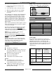
VL SERIES STEAMERS - GENERAL GENERAL Boiler Code Descriptions INTRODUCTION Steam Cooking Large capacity pressure steamers offer an efficient way to produce a wide variety of foods in small portions or larger batches. Steamers can be used to cook fresh foods, blanch foods for complete cooking later or will steam defrost and cook frozen foods. Cooking with steam assures the food will retain its maximum color, flavor and nutritional value with the least expenditure of energy and labor.
VL SERIES STEAMERS - GENERAL This causes several problems: 1. Reduce the heat transfer efficiency of the heating system. 2. Cause premature failure of Electric heaters. 3. Water level probes will give false readings. 4. Thermostat bulbs will sense temperature incorrectly. NOTE: Adaptors vary between manufacturers. An example of one adaptor type is pictured below.
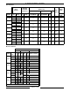
VL SERIES STEAMERS - GENERAL Gas Steamers LINE PRESSURE MANIFOLD PRESSURE INPUT (BTU/HR) (INCHES W.C.) AMPS (INCHES W.C.) NATURAL LOAD PROPANE (WATTS) MAX MODEL NAT. PROP.
VL SERIES STEAMERS - GENERAL Also, the ignition control module ON/OFF/RESET switch must be in the ON position to operate. This switch is located on the upper left side of the electrical control box for the ignition control module. A red light will illuminate when the switch is in the ON position. DO NOT ATTEMPT TO MANUALLY LIGHT THE PILOT IN AN AUTOMATIC TYPE IGNITION SYSTEM. STEAMER OPERATION Ensure that all utility connections to the steamer have been made and are turned on.
VL SERIES STEAMERS - GENERAL Observe water level gauge glass to verify that water is in boiler and that the level in the gauge glass is about half full. Both valves on the gauge glass assembly must be open to fill the gauge. When the water reaches the minimum level, the steam solenoid valve will open, allowing steam to enter the steam coil in the heat exchanger tank and begin heating the water. After approximately 20 minutes, a sufficient amount of pressurized steam should be present for cooking product.
VL SERIES STEAMERS - GENERAL 2. Standard A. 3. Set the timer to the desired cooking time. The timer must be set past five minutes to change the state of the timer control micro switch contacts. If preheating is desired, allow five to ten minutes (recommended) of additional time at the beginning of the cook cycle. The length of time will vary with the type, size, temperature and condition (frozen or thawed) of the product and must be determined from experience. B.
VL SERIES STEAMERS - GENERAL 4. Prevent A. Set the timer to the desired cooking time. The timer must be set past five minutes to change the state of the timer control micro switch contacts. B. Pull the steam control arm handle forward and lock it by pulling the handle down. This opens the steam inlet gate valve, allowing steam to enter the compartment. C. Press the compartment power switch to supply power to the compartment controls.
VL SERIES STEAMERS - GENERAL COMPONENT FUNCTION CABINET BASE BOILER CONTROLS Water Level Gauge Assembly . . . . . . . . . . . . . . . Water Level Control and Level Sensing Probes . . . . . . . . . . . Boiler Fill Solenoid Valve . . . . . . . . Cold Water Condenser Solenoid Valve . . . . . . . . . . . . . . . . . Permits a visual confirmation the water level is being maintained in boiler during operation. The correct water level is a point one-half of the height of the glass.
VL SERIES STEAMERS - GENERAL Handhole Cover Assembly . . . . . . . When unbolted and removed, allows internal examination and cleaning of boiler shell and its components if required. Boiler Pressure Gauge . . . . . . . . . . Indicates the amount of steam pressure in the boiler. Check Valve . . . . . . . . . . . . . . . . . . . On models with the delime piping assembly option, prevents the ejection of hot water and steam out of the delime funnel if the manual delime fill valve were to be opened.
VL SERIES STEAMERS - GENERAL COOKING COMPARTMENT CONTROLS The top half of the steamer consists of two to three separate cooking compartments depending on the model. Each compartment functions independently with its own set of controls. Power is supplied to the controls through the compartment power switch and the cooking timer control micro switch contacts.
VL SERIES STEAMERS - REMOVAL AND REPLACEMENT OF PARTS REMOVAL AND REPLACEMENT OF PARTS COMPONENT LOCATIONS Page 14 of 88
VL SERIES STEAMERS - REMOVAL AND REPLACEMENT OF PARTS Page 15 of 88
VL SERIES STEAMERS - REMOVAL AND REPLACEMENT OF PARTS COOKING COMPARTMENT CONTROLS - COMPONENT CONFIGURATIONS 1. Prevent thermal switch, inlet steam gate valve, steam exhaust solenoid (shown above) valve, steam control arm solenoid, timer, buzzer and power switch with light. Does not use a steam trap. 2. Automatic same as prevent except does not include steam exhaust solenoid valve but does include an exhaust steam gate valve and two steam traps. 3.
VL SERIES STEAMERS - REMOVAL AND REPLACEMENT OF PARTS WATER LEVEL CONTROLS LOW LEVEL CUT OFF AND DIFFERENTIAL WARNING: DISCONNECT THE ELECTRICAL POWER TO THE MACHINE AT THE MAIN CIRCUIT BOX. PLACE A TAG ON THE CIRCUIT BOX INDICATING THE CIRCUIT IS BEING SERVICED. 4. Slide the glass tube upwards until the bottom of the tube is clear of the fitting and lift it out. 5. When reinstalling the tube use new sealing washers. Do not over tighten the packing nuts; it could break the gauge glass. 6.
VL SERIES STEAMERS - REMOVAL AND REPLACEMENT OF PARTS BOILER ASSEMBLY HIGH LIMIT THERMOSTAT WARNING: DISCONNECT THE ELECTRICAL POWER TO THE MACHINE AT THE MAIN CIRCUIT BOX. PLACE A TAG ON THE CIRCUIT BOX INDICATING THE CIRCUIT IS BEING SERVICED. WARNING: DISCONNECT THE ELECTRICAL POWER TO THE MACHINE AT THE MAIN CIRCUIT BOX. PLACE A TAG ON THE CIRCUIT BOX INDICATING THE CIRCUIT IS BEING SERVICED. WARNING: SHUT OFF THE GAS BEFORE SERVICING THE UNIT. 1. Open the cabinet base doors. 2.
VL SERIES STEAMERS - REMOVAL AND REPLACEMENT OF PARTS BOILER FILL AND COLD WATER CONDENSER SOLENOID VALVES WARNING: DISCONNECT THE ELECTRICAL POWER TO THE MACHINE AT THE MAIN CIRCUIT BOX. PLACE A TAG ON THE CIRCUIT BOX INDICATING THE CIRCUIT IS BEING SERVICED. 1. Turn off the water supply to the steamer. 2. Open the cabinet base doors and remove the two screws at the top of the boiler control box and allow cover to drop down.
VL SERIES STEAMERS - REMOVAL AND REPLACEMENT OF PARTS COMPARTMENT GASKET AND DOOR SCREW NUT, DOOR AND BUSHINGS 4. Turn screw handle fully counterclockwise and remove from door. 5. Remove screws mounting the pressure bar to the backside of the compartment door. Gasket NOTE: A compression spring is mounted behind each screw. Set aside for reuse. 1. Open the compartment door to be replaced. 6. 2. Remove screws securing the gasket retaining plate to the gasket.
VL SERIES STEAMERS - REMOVAL AND REPLACEMENT OF PARTS HEATER CONTACTORS REGENERATED STEAM MODELS (STEAM COIL) WARNING: DISCONNECT THE ELECTRICAL POWER TO THE MACHINE AT THE MAIN CIRCUIT BOX. PLACE A TAG ON THE CIRCUIT BOX INDICATING THE CIRCUIT IS BEING SERVICED. 1. Open the cabinet base doors, remove the two screws from the contactor box cover and lift cover off. 2. Disconnect the electrical lead wires to the coil and the power supply wires from the contactor being replaced. 3. 4.
VL SERIES STEAMER - SERVICE PROCEDURES AND ADJUSTMENTS SERVICE PROCEDURES AND ADJUSTMENTS WARNING: CERTAIN PROCEDURES IN THIS SECTION REQUIRES ELECTRICAL TEST OR MEASUREMENTS WHILE POWER IS APPLIED TO THE MACHINE. EXERCISE EXTREME CAUTION AT ALL TIMES. IF TEST POINTS ARE NOT EASILY ACCESSIBLE, DISCONNECT POWER, ATTACH TEST EQUIPMENT AND REAPPLY POWER TO TEST. NOTE: Boiler water capacities vary between seven to nine gallons for both gas and electric models depending on the boiler size and BTU/KW rating.
VL SERIES STEAMER - SERVICE PROCEDURES AND ADJUSTMENTS 10. Cooking compartment timers are to be in the OFF position. Turn the boiler switch ON and open water valve if necessary. B. 11. Boiler is to operate under pressure for 90 minutes or per the instructions for the chemical in use. Models without Blowdown Timer - Turn off the incoming water supply. Turn the power switch ON to close the drain valve. Open the deliming assembly valve and pour the deliming solution into the port.
VL SERIES STEAMER - SERVICE PROCEDURES AND ADJUSTMENTS WATER LEVEL CONTROL(S) TEST Loose electrical connections may prevent the heat from coming on or may cause the boiler to overfill. An accumulation of lime scale on or near the water level sensing probes may cause them to retain water (moist) on the probe surface and give a false reading. Also, a cracked or damaged insulator may give a false reading. These conditions may prevent the boiler from filling or cause dry firing.
VL SERIES STEAMER - SERVICE PROCEDURES AND ADJUSTMENTS B. 3. 4. With the boiler empty, check the voltage across terminals 9 & 10. Meter should read 300 to 350VAC. If voltage is correct proceed to step 3. If voltage reading is approximately 30VAC then the internal contactor is energized but the probes are scaled over and moist and/or have a damaged insulator giving a false reading.
VL SERIES STEAMER - SERVICE PROCEDURES AND ADJUSTMENTS Two slotted and square headed adjustment screws extend through the top of the switch case. A pressure scale and indicating pointers are visible through the sight glass window to indicate the approximate pressure setting. The adjustment screw directly above the right side pointer changes the cut-out (off) set point and the adjustment screw directly above the left side pointer changes cut-in (on) set point.
VL SERIES STEAMER - SERVICE PROCEDURES AND ADJUSTMENTS HIGH LIMIT THERMOSTAT WARNING: DISCONNECT THE ELECTRICAL POWER TO THE MACHINE AT THE MAIN CIRCUIT BOX. PLACE A TAG ON THE CIRCUIT BOX INDICATING THE CIRCUIT IS BEING SERVICED. Remove thermostat (bi-metallic disk type) as outlined under “HIGH LIMIT THERMOSTAT” in “REMOVAL AND REPLACEMENT OF PARTS”. Inspect the temperature sensing side of thermostat for corrosion or rust. Clean mounting and thermostat surfaces before remounting or replacing.
VL SERIES STEAMER - SERVICE PROCEDURES AND ADJUSTMENTS If the blowdown operation appears to function sluggishly or not at all, considerable scalants may be lodged in the drain pipe and/or the valve. Disconnect the valve from the drain line and inspect both the valve and the drain pipe fixed to the boiler. If considerable scalants or lime build up is apparent, then not only the valve, but also the boiler and water level probes must be thoroughly cleaned.
VL SERIES STEAMER - SERVICE PROCEDURES AND ADJUSTMENTS C. D. 3. One or more electric heating elements malfunctioning. See “HEATING ELEMENTS” B. One or more heater contactors not pulling in to power heating elements. C. If steamer operates under three phase power, then check line for all phases. D. 5. Gas orifice clogged or obstructed around air shutter. It is possible for debris to become lodged in the small gas orifice opening over time.
VL SERIES STEAMER - SERVICE PROCEDURES AND ADJUSTMENTS NOTE: If adjustments in gas or pilot pressure settings are made, always replace the adjustment cover screw to assure proper gas control operation. Check the thermocouple output voltage as follows: 1. Turn the power switch OFF and disconnect the thermocouple from the gas combination control valve. 2. Check the thermocouple DC millivolt output with a VOM. If a meter is not available, replace the thermocouple with a new one and check operation again.
VL SERIES STEAMER - SERVICE PROCEDURES AND ADJUSTMENTS D. With the thermocouple disconnected, connect the meter leads to the tube and threaded end. Turn the power switch ON and light the pilot. Hold down the OFF/PILOT/ON knob and allow the pilot to heat the thermocouple for one to two minutes. Take an open circuit reading and compare with the chart below. 1) 3. 3. Loosen the set screw on the burner being adjusted.
VL SERIES STEAMER - SERVICE PROCEDURES AND ADJUSTMENTS Once the pilot flame is confirmed, a 24 volt output from terminal one will be sent, allowing the main valve (cycling) coil of the combination valve to operate at the request of the cycling pressure switch. A. Check to ensure that all electrical terminal connections on the ignition control module and the ignitor are clean and tight. If loose connections are found, make the necessary adjustments. B.
VL SERIES STEAMER - SERVICE PROCEDURES AND ADJUSTMENTS 2) 3) 3. 4. If a spark from ignitor is present but does not ignite gas before the ignition control module locks out, (90 sec.) there may not be enough gas in the line for ignition. Verify the gas supply and gas combination control valve are both on. Turn the ignition control modules re-set switch OFF then ON to reset the module. Sparking should then resume to ignite gas. The module may need reset several times before ignition takes place.
VL SERIES STEAMER - SERVICE PROCEDURES AND ADJUSTMENTS 7. 8. Once the correct pressure has been set, turn the power switch OFF, replace the adjustment screw cap and 1/8 inch NPT plug (pressure tap) on the outlet side of the valve. Check for proper operation. DIRECT STEAM MODELS HEATER CONTACTORS WARNING: DISCONNECT THE ELECTRICAL POWER TO THE MACHINE AT THE MAIN CIRCUIT BOX. PLACE A TAG ON THE CIRCUIT BOX INDICATING THE CIRCUIT IS BEING SERVICED.
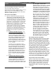
VL SERIES STEAMER - SERVICE PROCEDURES AND ADJUSTMENTS NUMBER KW TOTAL OF PER VOLTAGE KW ELEMENTS ELEMENT AMPERAGE PER LINE 1 PH 3 PH RESISTANCE PER ELEMENT (OHMS) 208 18 2 9 87 50 14.42 240 18 2 9 75 44 19.20 480 18 2 9 22 76.80 *220/380 240/415 18 2 9 25 19.20 208 24 2 12 116 68 10.82 240 24 2 12 100 58 14.40 480 24 2 12 29 57.60 *220/380 240/415 24 2 12 34 14.40 208 36 4 9 100 14.42 240 36 4 9 87 19.20 480 36 4 9 44 76.
VL SERIES STEAMER - SERVICE PROCEDURES AND ADJUSTMENTS THERMAL SWITCH - PREVENT AND AUTOMATIC MODELS D. If the cooking cycle is started normally, but the red light and timer do not come on or an abnormal amount of time elapses before they come on, then the load compensator is set too high.
VL SERIES STEAMER - SERVICE PROCEDURES AND ADJUSTMENTS STEAM GATE VALVE(S) On all models, each cooking compartment has its own mechanical steam gate valve that supplies steam to the cooking compartment when the steam control arm handle is pulled forward. The Prevent models use a solenoid valve to exhaust steam from the compartment whereas the Automatic, Standard and Manual models use an additional steam gate valve to exhaust steam when the steam control arm handle is returned to the rear.
VL SERIES STEAMER - ELECTRICAL OPERATION ELECTRICAL OPERATION WATER LEVEL CONTROLS Solid State - Low level Cut-Off & Differential Control The steamer is equipped with three water level sensing probes (high, low and low level cut-off) and a single water level control board. The water level control board performs two functions: 1. Provide low level cut-off protection to shut off the heat source in case the water level drops below the low level cut-off (LLCO) probe. 2.
VL SERIES STEAMER - ELECTRICAL OPERATION Solid State - Auxiliary Low Level Cut-Off This control serves as a safety backup to the main water level control (WLC) board to meet Cal-Code and CSD-1 code requirements. The auxiliary control provides auxiliary low level cut-off protection to shut off the heat source in case the water level drops below the low level cut-off (LLCO) probe. A single LLCO probe is connected to the auxiliary control.
VL SERIES STEAMER - ELECTRICAL OPERATION Electro Mechanical - Low level Cut-Off & Differential Control The steamer is equipped with three water level sensing probes (high, low and low level cut-off), a differential level control (1G1GO) and a low level cut-off control (1D1DO). The low-level cut-off is an additional control that is identical to the differential level control but serves as the safety backup to shut off the heat source in case the water level drops below the low level cut-off (LLCO) probe.
VL SERIES STEAMER - ELECTRICAL OPERATION Electro Mechanical - Auxiliary Low Level Cut-Off This control serves as a safety backup to the main low level cut-off (LLCO) control to meet Cal-Code requirements. The operation of the auxiliary control is identical to the main low level cut-off control but performs a single function: 1) Provide auxiliary low level cut-off protection to shut off the heat source in case the water level drops below the low level cut-off (LLCO) probe.
VL SERIES STEAMER - ELECTRICAL OPERATION SEQUENCE OF OPERATION GAS MODELS This sequence of operation is written for steamers with electronic ignition, solid state water level controls, CSD-1 (code) boiler controls option and with Prevent cooking compartment controls. Refer to schematic diagram numbers 3928 and 3929 for a boiler control schematic and 3962 for a schematic and wiring diagram on Prevent cooking compartment controls.
VL SERIES STEAMER - ELECTRICAL OPERATION 3. C. Water level reaches LLCO (low water level cutoff) probe for the water level control and to the auxiliary LLCO probe for the auxiliary low level cut-off control. A. Power to terminal 9 on the water level control. 1) B. D. LLCO relay energizes, LLCO-2 (N.O.) contacts close and LED lights. Power to terminal LLCO on the auxiliary low water level cut-off control. 1) E. 7. LLCO relay energizes, LLCO-2 (N.O.) contacts close and LED lights.
VL SERIES STEAMER - ELECTRICAL OPERATION A. Cook Cycle 1. A Cook cycle should not be started, until the initial fill and preheat is completed, in order for the boiler steam pressure to be within operational limits. A. Insert product into steamer. B. Compartment door is closed and screw handle tightened down. C. 4. Cooking timer is manually turned off. 5. Compartment power switch is turned OFF, buzzer is de-energized and power is removed from the common side of micro switch SW1. 6.
VL SERIES STEAMER - ELECTRICAL OPERATION 4. 2) 1) HL-3 opens. 2) Fill solenoid de-energized and water stops flowing into tank. 3) HL LED goes out. The water refill cycle will occur whenever the water level is below the low level probe and will not affect the operation of either the preheat or cook cycle.
VL SERIES STEAMER - ELECTRICAL OPERATION 1) NOTE: Power the internal contactors on the low level cut-off and auxiliary low level cut-off will remain, until the water level drops below the LLCO probes or the power switch is turned OFF. 4. Manual reset switch is pressed (momentary). A. The auxiliary heater contactor is energized supplying power to the heating elements and the heat light (amber) comes on. 1) B. Internal relay on manual reset switch is energized. 1) 5.
VL SERIES STEAMER - ELECTRICAL OPERATION F. Once compartment temperature reaches approximately 180°F thermal switch closes and supplies power L1 (HOT) to: 1) WATER REFILL (AFTER INITIAL FILL) 1. Water level drops below low level probe (LL). A. Steam exhaust solenoid valve (N.O.) energized and closes. 1) NOTE: Even though steam exhaust solenoid valve is closed, a small opening exists in the “guillotine” blade of the valve to allow “limited free venting” of condensate during a cook cycle. 2) 3) 2.
VL SERIES STEAMER - ELECTRICAL OPERATION PAGE PURPOSELY LEFT BLANK Page 48 of 88
VL SERIES STEAMER - ELECTRICAL OPERATION SCHEMATICS, GAS STEAMERS, BOILER CONTROLS VL2G AND VL3G - PREVENT, AUTOMATIC, STANDARD AND MANUAL Manual Ignition, Standard Controls Page 49 of 88
VL SERIES STEAMER - ELECTRICAL OPERATION Electronic Ignition, Standard Controls Page 50 of 88
VL SERIES STEAMER - ELECTRICAL OPERATION Manual Ignition, CSD-1 Code Controls Page 51 of 88
VL SERIES STEAMER - ELECTRICAL OPERATION Electronic Ignition, CSD-1 Code Controls Page 52 of 88
VL SERIES STEAMER - ELECTRICAL OPERATION Page 53 of 88
VL SERIES STEAMER - ELECTRICAL OPERATION WIRING DIAGRAMS, GAS STEAMERS, BOILER CONTROLS VL2G AND VL3G - PREVENT, AUTOMATIC, STANDARD AND MANUAL Manual Ignition, Standard Controls Page 54 of 88
VL SERIES STEAMER - ELECTRICAL OPERATION Page 55 of 88
VL SERIES STEAMER - ELECTRICAL OPERATION Electronic Ignition, Standard Controls Page 56 of 88
VL SERIES STEAMER - ELECTRICAL OPERATION Page 57 of 88
VL SERIES STEAMER - ELECTRICAL OPERATION Manual Ignition, CSD-1 Code Controls Page 58 of 88
VL SERIES STEAMER - ELECTRICAL OPERATION Page 59 of 88
VL SERIES STEAMER - ELECTRICAL OPERATION Electronic Ignition, CSD-1 Code Controls Page 60 of 88
VL SERIES STEAMER - ELECTRICAL OPERATION Page 61 of 88
VL SERIES STEAMER - ELECTRICAL OPERATION SCHEMATICS, ELECTRIC STEAMERS, BOILER CONTROLS VL2E AND VL3E - PREVENT, AUTOMATIC, STANDARD AND MANUAL Auto Blowdown, Standard Controls Page 62 of 88
VL SERIES STEAMER - ELECTRICAL OPERATION Auto Blowdown, Cal-Code Controls Page 63 of 88
VL SERIES STEAMER - ELECTRICAL OPERATION WIRING DIAGRAMS, ELECTRIC STEAMERS, BOILER CONTROLS VL2E AND VL3E - PREVENT, AUTOMATIC, STANDARD AND MANUAL Auto Blowdown, Standard Controls (contactor - 1 std.
VL SERIES STEAMER - ELECTRICAL OPERATION Page 65 of 88
VL SERIES STEAMER - ELECTRICAL OPERATION Auto Blowdown, Standard Controls (contactors - 2 std.
VL SERIES STEAMER - ELECTRICAL OPERATION Page 67 of 88
VL SERIES STEAMER - ELECTRICAL OPERATION Manual Blowdown, Cal-Code Controls (contactors - 1 std. 1 aux.
VL SERIES STEAMER - ELECTRICAL OPERATION Page 69 of 88
VL SERIES STEAMER - ELECTRICAL OPERATION Auto Blowdown, Cal-Code Controls ( contactors - 1 std. 1 aux.
VL SERIES STEAMER - ELECTRICAL OPERATION Page 71 of 88
VL SERIES STEAMER - ELECTRICAL OPERATION Auto Blowdown, Cal-Code Controls (contactors - 2 std. 2 aux.
VL SERIES STEAMER - ELECTRICAL OPERATION Page 73 of 88
VL SERIES STEAMER - ELECTRICAL OPERATION Manual Blowdown, Cal-Code Controls (contactors - 2 std. 2 aux.
VL SERIES STEAMER - ELECTRICAL OPERATION Page 75 of 88
VL SERIES STEAMER - ELECTRICAL OPERATION WIRING DIAGRAMS, ELECTRIC HEATER CIRCUITS VL2E AND VL3E - PREVENT, AUTOMATIC, STANDARD AND MANUAL Standard and Cal-Code/CSD-1 Controls Page 76 of 88
VL SERIES STEAMER - ELECTRICAL OPERATION SCHEMATIC AND WIRING DIAGRAMS, DIRECT STEAMERS, CABINET BASE VL2D AND VL3D - PREVENT, AUTOMATIC, STANDARD AND MANUAL See “SCHEMATIC AND WIRING DIAGRAMS - COMPARTMENT CONTROLS” Page 77 of 88
VL SERIES STEAMER - ELECTRICAL OPERATION WIRING DIAGRAMS, REGENERATED STEAMERS, BOILER CONTROLS VL2R AND VL3R - PREVENT, AUTOMATIC, STANDARD AND MANUAL Manual Blowdown (Older Models) Page 78 of 88
VL SERIES STEAMER - ELECTRICAL OPERATION Auto Blowdown (Older Models) Page 79 of 88
VL SERIES STEAMER - ELECTRICAL OPERATION SCHEMATIC AND WIRING DIAGRAMS - COMPARTMENT CONTROLS Prevent Page 80 of 88
VL SERIES STEAMER - ELECTRICAL OPERATION Automatic Page 81 of 88
VL SERIES STEAMER - ELECTRICAL OPERATION Standard Page 82 of 88
VL SERIES STEAMER - ELECTRICAL OPERATION Manual NO ELECTRICAL COMPONENTS ARE USED WITH THE MANUAL COMPARTMENT CONTROLS OPTION. THE CONTROLS CONSIST OF A MANUAL COOKING TIMER AND MANUAL STEAM CONTROL ARM TO CLOSE AND OPEN THE STEAM GATE VALVES.
VL SERIES STEAMER - TROUBLESHOOTING TROUBLESHOOTING ALL MODELS WARNING: CERTAIN PROCEDURES IN THIS SECTION REQUIRE ELECTRICAL TESTS OR MEASUREMENTS WHILE POWER IS APPLIED TO THE MACHINE. EXERCISE EXTREME CAUTION AT ALL TIMES. IF TEST POINTS ARE NOT EASILY ACCESSIBLE, DISCONNECT POWER, ATTACH TEST EQUIPMENT AND REAPPLY POWER TO TEST. SYMPTOM Compartment leaks water around door. Cold water condenser not operating properly. POSSIBLE CAUSES 1. Drain screen clogged. 2.
VL SERIES STEAMER - TROUBLESHOOTING SYMPTOM Boiler base will not heat or build pressure. POSSIBLE CAUSES 1. Check incoming voltage. 2. Boiler not filled - check fill solenoid for power, clogging or malfunction. 3. Water Level Control malfunction. HL-3 relay not energizing or contacts not closing to power boiler fill solenoid. 4. Water too “pure” for probes to properly conduct electricity. 5. Contactor malfunction (electric only). 6. Heating element inoperative (electric only). 7.
VL SERIES STEAMER - TROUBLESHOOTING SYMPTOM Cooking timer motor does not run. POSSIBLE CAUSES 1. Timer not getting power. 2. Timer motor inoperative. 1. Cooking timer malfunction. 2. Buzzer malfunction. Compartment red light and timer do not come on; excessive time elapses before they come on; timer stops, the red light goes out, and the buzzer does not sound after compartment exhausts steam; time is set as usual for the product and the product is overcooked. 1.
VL SERIES STEAMER - TROUBLESHOOTING GAS MODELS ONLY SYMPTOM Burner won’t light. POSSIBLE CAUSES 1. Gas not on. 2. Ignition control module reset switch in the OFF position or malfunctioning. 3. Ignition module not receiving power. Check ignition module transformer for 24VAC output to module on automatic ignition systems. 4. Steamer not properly grounded and/or polarity of incoming power is incorrect on automatic ignition systems. 5. Low incoming gas pressure.
VL SERIES STEAMER - TROUBLESHOOTING SYMPTOM Pilot not lit or goes out. Spark Ignitor not sparking. Form 24650 (May 1999) POSSIBLE CAUSES 1. Gas not on. 2. Pilot going out due to drafts, excess steam from drain or steamer not level. Improper venting can direct the pilot flame away from thermopile or flame sensor. 3. Low incoming gas pressure. See “GAS MANIFOLD PRESSURE ADJUSTMENT” in “SERVICE PROCEDURES”. 4. Pilot not adjusted correctly.