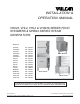
INSTALLATION & OPERATION MANUAL VHX24, VHL2, VHL3 & VH3616 SERIES FOOD STEAMERS & MHB24 SERIES STEAM GENERATORS MODELS VHX24E VHX24E5 VHX24G VHX24G5 VHX24D VHX24D5 VHL2G VHL3G VHL2E VHL3E VHL2D VHL3D MHB24E MHB24G VH3616G VH3616E VH3616D ML-136033 ML-136034 ML-136031 ML-136032 ML-136035 ML-136036 ML-126323 ML-126324 ML-126855 ML-126856 ML-126858 ML-126859 ML-126857 ML-114954 ML-136000 ML-136001 ML-136002 Model MHB24G Model VHX24E Model VHL2G For additional information on Vulcan-Hart or to locate an auth
IMPORTANT FOR YOUR SAFETY THIS MANUAL HAS BEEN PREPARED FOR PERSONNEL QUALIFIED TO INSTALL GAS EQUIPMENT, WHO SHOULD PERFORM THE INITIAL FIELD START-UP AND ADJUSTMENTS OF THE EQUIPMENT COVERED BY THIS MANUAL. POST IN A PROMINENT LOCATION THE INSTRUCTIONS TO BE FOLLOWED IN THE EVENT THE SMELL OF GAS IS DETECTED. THIS INFORMATION CAN BE OBTAINED FROM THE LOCAL GAS SUPPLIER.
TABLE OF CONTENTS GENERAL 5 INSTALLATION 5 Unpacking 5 Installation Codes and Standards 5 Leveling — All Steamers & Steam Generators 6 Plumbing Connections — All Steamers & Steam Generators 6 Water Supply Connection 6 Water Requirements 6 Drain Connection 6 Location — Gas Powered Steamers & Steam Generators 7 Gas Supply Connection 7 Testing the Gas Supply System 8 Flue Gas Exhaust 8 Electrical Connection — Gas Steamers & Steam Generators 8 Location — Electric Steamers & Steam Gen
Standard Automatic Compartment Controls — VHL2 & VHL3 Steamers Preheating Operating VHL2 & VHL3 Steamers with Standard Automatic Compartment Controls Pre-Vent Compartment Controls — VHL2 & VHL3 Steamers Operating VHL2 & VHL3 with Pre-Vent Compartment Controls Selection of Pans for Steam Cooking in VHL2 & VHL3 Steamers Cooking Hints Suggested Cooking Guidelines Cleaning Cooking Compartment Drains Boiler Blowdown Compartments Door Gaskets Leave Compartment Doors Open Guidelines for Maintaining Stainless Steel
Installation, Operation and Care of VHX24, VHL2, VHL3 & VH3616 SERIES FOOD STEAMERS & MHB24 SERIES STEAM GENERATORS SAVE THESE INSTRUCTIONS FOR FUTURE USE GENERAL Vulcan food steamers and steam generators are produced with quality workmanship and material. Proper installation, usage and maintenance will result in many years of satisfactory performance. It is suggested that you thoroughly read this entire manual and carefully follow all of the instructions provided.
LEVELING — ALL STEAMERS & STEAM GENERATORS Position the steamer or steam generator in its final installed location. Place a level on the horizontal area of the cabinet. Adjust the feet to level the steamer or steam generator in both the left-to-right and front-to-rear directions. On VHX steamers only, elevate the front 1/16" to 1/8" (0.2 cm to 0.3 cm) to give proper drainage by rotating the adjusting nut on the rear legs in the proper direction 1 to 11/2 turns.
Temperatures in the boiler can briefly reach as high as 212°F (100°C). Local codes require that the temperature of drain water be no greater than 140°F (60°C). At the end of the day, when purging the boilers, some provision for lowering the water temperature must be provided by the user or installer to meet this code requirement. LOCATION — GAS POWERED STEAMERS & STEAM GENERATORS The equipment area must be kept free and clear of combustible substances.
TESTING THE GAS SUPPLY SYSTEM When the gas supply pressure exceeds 1/2 psig (3.45 kPa), the steamer and its individual shutoff valve must be disconnected from the gas supply piping system. When the gas supply pressure is 1/2 psig (3.45 kPa) or less, the steamer should be isolated from the gas supply system by closing its individual manual shutoff valve. FLUE GAS EXHAUST DO NOT obstruct the flow of flue gases from the flue located on the rear of the steamer.
LOCATION — ELECTRIC STEAMERS & STEAM GENERATORS Position the steamer or steam generator in its final location. The recommended clearance for proper operation is 36" (91.4 cm) at the front. The required clearance from combustible or non-combustible construction is 0" at the sides and back. The recommended clearance for service access is 18" (45.7 cm) at the sides and back. Clearances less than 18" may require removal of adjacent equipment during servicing at customer's expense.
CONNECTION OF OTHER STEAM COOKING EQUIPMENT TO AN ELECTRIC OR GAS BOILER Steam can be supplied to additional steam equipment from the auxiliary steam port on the boiler, or Steam Line Connection (Fig. 1). When additional equipment is added, appliance efficiency will be affected. To be certain that you will be operating at optimum efficiency, contact the Vulcan-Hart sales representative in your area for steam boiler horsepower calculations.
STARTUP TEST RUN — VHX24 & VH3616 SERIES STEAMERS Refer to the OPERATION section for more information on VHX24 compartment and boiler controls. WARNING: THE STEAMER AND ITS PARTS ARE HOT. CLEANING OR SERVICING THE STEAMER. USE CARE WHEN OPERATING, WARNING: THE COOKING COMPARTMENTS CONTAIN LIVE STEAM. OPENING EACH DOOR. STAY CLEAR WHILE After the steamer is installed and proper service connections have been made, thoroughly test the steamer before operation.
13. Set both timer dials to 2 minutes. The green ready lights will go off, the red cooking lights will come on and steam will be heard entering the compartments. 14. Wait until 1 minute is left on the timers. 15. Open each door and observe that steam has stopped entering into each compartment. The red cooking lights remain on. 16. Close the compartment doors. Steam generation and timers resume. Make sure that steam from the drain is being cooled by water from the cold water condenser. 17.
8. Verify that the gas supply is adequate: • Monitor gas pilot pressure as the main burner lights. Sufficient gas supply will not allow the gas pilot pressure to drop when the main burner gas valve is energized. • Gas pilot pressure dropping more than 0.25" W.C. indicates an insufficient supply. Larger diameter (ID) gas supply piping to the steamer must be used. • Turn on other gas equipment that shares the gas supply line to the steamer. Verify gas pilot pressure does not drop more than 0.25" W.C.
OPERATION BOILER CONTROLS — GAS (Figs. 2, 3) or ELECTRIC (Figs. 2, 4) Power Switch • Press [ I ] to power the controls and begin filling the boiler. POWER SWITCH HIGH PRESSURE LIGHT • Press [ O ] to turn the controls and the steamer off. The boiler automatically blows down for about 5 minutes. LOW WATER LIGHT RESET SWITCH (GREEN) High Pressure Light • Is lit after [ I ] is pressed and stays on during fill. Goes off after the reset switch is pressed (when green light is lit).
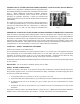
Gas Boiler (Fig. 3) PRESSURE RELIEF VALVE GAS VALVE PROBE HOUSING BLOWDOWN VALVE MANUAL VALVES WATER INLET VALVE WATER LEVEL GAUGE PL-41749-1 Fig. 3 Electric Boiler (Fig. 4) PRESSURE RELIEF VALVE PROBE HOUSING BLOWDOWN VALVE MANUAL VALVES CONDENSATE WATER INLET VALVE WATER LEVEL GAUGE BOILER FILL VALVE PL-41748-1 Fig. 4 Probe Housing Blowdown Valve • Open periodically (monthly) to blow down the probes and to remove sediment and scale buildup. • Located toward the back left side.
COMPARTMENT CONTROLS — VHX24 & VH3616 SERIES STEAMERS (Fig. 5) WARNING: THE STEAMER AND ITS PARTS ARE HOT. CLEANING OR SERVICING THE STEAMER. USE CARE WHEN OPERATING, WARNING: THE COOKING COMPARTMENTS CONTAIN LIVE STEAM. OPENING EACH DOOR. STAY CLEAR WHILE Ready Light (Green) — Indicates the steamer is ready for the cooking cycle. READY LIGHT READ Y COO KING COOKING LIGHT Cooking Light (Red) — Indicates the steamer is in the cooking phase. TIMER TIME Timer R — Sets the desired cooking time.
OPERATING VHX24 & VH3616 SERIES STEAMERS 1. Press [ I ] and wait until the boiler is filled to the required level. Both the low water and high pressure indicator lights are lit. 2. Press the reset switch when its green indicator light is lit. Both the low water and high pressure indicator lights must go off before heating will begin. 3. Wait 10 minutes before starting a cooking operation. 4.
STANDARD AUTOMATIC COMPARTMENT CONTROLS — VHL2 & VHL3 STEAMERS (Fig. 6) WARNING: THE STEAMER AND ITS PARTS ARE HOT. CLEANING OR SERVICING THE STEAMER. USE CARE WHEN OPERATING, WARNING: THE COOKING COMPARTMENTS CONTAIN LIVE STEAM. OPENING EACH DOOR. STAY CLEAR WHILE Door Latch • Holds the door closed. Door Screw Handle (Not Shown) • Seals door the gasket against the cabinet. Cooking Time Control • Sets the desired cooking time (0 to 60 minutes).
OPERATING VHL2 & VHL3 STEAMERS WITH STANDARD AUTOMATIC COMPARTMENT CONTROLS 1. Prepare vegetables, fruits, meats, seafood and poultry as you would for steam cooking or cooking in water: clean, separate, cut, remove stems, etc., and place in a pan. 2. Place loaded pans in the compartment and close the compartment door. Turn the door screw handle clockwise to seal the door gasket. Normal pressure will seal the compartment; however, a new gasket may require additional pressure after it becomes heated.
PRE-VENT ™ COMPARTMENT CONTROLS — VHL2 & VHL3 STEAMERS (Fig. 7) WARNING: THE STEAMER AND ITS PARTS ARE HOT. CLEANING OR SERVICING THE STEAMER. USE CARE WHEN OPERATING, WARNING: THE COOKING COMPARTMENTS CONTAIN LIVE STEAM. OPENING EACH DOOR. STAY CLEAR WHILE Door Latch • Holds the door closed. Door Screw Handle (Not Shown) • Seals the door gasket against the cabinet. Cooking Time Control COOKING TIME CONTROL DOOR LATCH • Sets the desired cooking time (0 to 60 minutes).
OPERATING VHL2 & VHL3 WITH PRE-VENT COMPARTMENT CONTROLS 1. Prepare vegetables, fruits, meats, seafood and poultry as you would for steam cooking or cooking in water: clean, separate, cut, remove stems, etc., and place in a pan. 2. Place loaded pans in the compartment and close the compartment door. Turn the door screw handle clockwise to seal the door gasket. Normal pressure will seal the compartment; however, a new gasket may require additional pressure after it becomes heated.
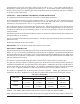
SELECTION OF PANS FOR STEAM COOKING IN VHL2 & VHL3 STEAMERS Vulcan Adapt-A-Pan TM steamer compartments (Fig. 8) are designed to accept combinations of the following perforated or solid cooking pans. PAN SELECTION — VHL2 & VHL3 STEAMERS Max Qty Pan Size Pan Depth 4 12" x 20" (30 cm x 51 cm) 6" (15 cm) 6 12" x 20" 4" (10 cm) 8 12" x 20" 21/ 2" ( 6 cm) 6 18" x 26" (46 cm x 66 cm) 1 (2.5 cm) (center support must be removed) 16 12" x 20" (not shown) Fig. 8 – 22 – 1 (2.
COOKING HINTS Spread food out evenly in pans and do not allow food to protrude above pans. This will interfere with steam circulation between pans in the compartment. Preheating of compartments is necessary for satisfactory results except for VHL2 & VHL3 steamers with Pre-Vent Automatic Controls. When time does not allow for defrosting of frozen vegetables, such as loose-pack peas, corn, diced carrots, etc.
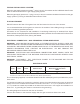
PRODUCTS TO BE COOKED IN PERFORATED PANS TIMER SETTING IN MINUTES WEIGHT PER PAN 10 to 12 5 to 6 3 Dozen 3 Dozen 4 4 to 6 21/ 2 Lb. (1 kg) 41/ 2 Lb. (2 kg) Lobster Tail, Frozen Lobster, Live, 10 to 12" (25.4 to 30.5 cm) 6 5 10 Lb. (4.5 kg) 4 Per Pan Salmon Fillets, Frozen, 8 Oz. (227 grams) Each 5 7 1/ 2 Lb. (3.4 kg) Scallops, Fresh 4 3 Lb. (1.4 kg) 3 to 5 4 Lb. (1.
PRODUCTS TO BE COOKED IN PERFORATED PANS TIMER SETTING IN MINUTES WEIGHT PER PAN Brussel Sprouts, Frozen 6 5 Lb. (2.3 kg) Cabbage, Fresh 1/6 Cut 8 5 Lb. (2.3 kg) Carrots Baby Whole, Frozen Crinkle Cut, Frozen Sliced, Fresh 8 7 to 8 11 7 Lb. (3.2 kg) 4 Lb. (1.8 kg) 9 Lb. (4.1 kg) Cauliflower, Flowerettes Frozen Fresh 6 7 to 8 4 Lb. (1.8 kg) 5 Lb. (2.3 kg) 7 5 Lb. (2.3 kg) 5 8 16 to 18 10 to 12 16 to 18 5 Lb. (2.3 kg) 27 Ears 80 Ears 18 Ears 54 Ears Peas, Green 6 5 Lb. (2.
CLEANING WARNING: DISCONNECT THE ELECTRICAL POWER TO THE MACHINE AND FOLLOW LOCKOUT/TAGOUT PROCEDURES BEFORE CLEANING. COOKING COMPARTMENT DRAINS Keep compartment drains running freely. Inspect compartment drains daily for blockage. Remove any particles or debris from the perforated strainer daily (or more often if needed). After cooking greasy foods or seafood, close the doors and operate each compartment for 15 to 30 minutes to flush any residual grease and oils down the compartment drain.
GUIDELINES FOR MAINTAINING STAINLESS STEEL SURFACES There are four things that can break down stainless steel and allow corrosion to develop: 1) abrasion, 2) deposits, 3) water and 4) chlorides. Avoid rubbing with steel pads, wire brushes or scrapers that can leave iron deposits on stainless steel. Instead, use plastic scouring pads or soft cloths. For stubborn stains, use products such as Cameo, Talc or Zud First Impression. Always rub parallel to the polish lines or with the grain.
MAINTENANCE WARNING: THE STEAMER AND ITS PARTS ARE HOT. USE CARE WHEN OPERATING, CLEANING OR SERVICING THE STEAMER. WARNING: THE COOKING COMPARTMENTS CONTAIN LIVE STEAM. STAY CLEAR WHILE OPENING EACH DOOR. WATER TREATMENT SYSTEM A water treatment system is recommended for steam generators. Refer to your supplier's manual for normal maintenance procedures for proper scale-free operation recommendations.
SCALE RELATED MAINTENANCE (GAS & ELECTRIC BOILERS) Periodic maintenance is necessary to keep your boiler clean and efficient. Initially, after three months of steamer usage, it is recommended that you have your Vulcan-Hart authorized servicer inspect the boiler and perform the descaler maintenance described below. Local water conditions and steamer usage will determine the frequency that this service must be repeated; however, a minimum recommendation is once a year.
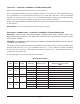
TROUBLESHOOTING SYMPTOMS POSSIBLE CAUSES High Pressure and Low Water lights do not come on when [ l ] is pressed. 1. Electrical power to the steamer is not on. 2. Power switch is not in the [ l ] position. Steamer will not fill. 1. If the Low Water light is on, the water supply valve may be off. Check water supply pressure. 2. Water filter is plugged. Refer to water filter manual. If symptom persists, contact Service. Steamer will not heat or build pressure. 1. 2. 3. 4. Water flows into compartment.
NOTES – 31 –
NOTES FORM 35419 (Dec. 2004) – 32 – PRINTED IN U.S.A.