INSTALLATION & OPERATION MANUAL Medium Duty Gas Griddles MODELS MODELS VCRG24-T WCRG24-T VCRG36-T WCRG36-T VCRG48-T WCRG48-T VCRG48-T ITW Food Equipment Group, LLC 3600 North Point Blvd. Baltimore, MD 21222 RETAIN THIS MANUAL FOR FUTURE USE FORM F-38305 (rev.
IMPORTANT FOR YOUR SAFETY THIS MANUAL HAS BEEN PREPARED FOR PERSONNEL QUALIFIED TO INSTALL GAS EQUIPMENT, WHO SHOULD PERFORM THE INITIAL FIELD START-UP AND ADJUSTMENTS OF THE EQUIPMENT COVERED BY THIS MANUAL. POST IN A PROMINENT LOCATION THE INSTRUCTIONS TO BE FOLLOWED IN THE EVENT THE SMELL OF GAS IS DETECTED. THIS INFORMATION CAN BE OBTAINED FROM THE LOCAL GAS SUPPLIER.
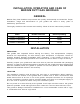
INSTALLATION, OPERATION AND CARE OF MEDIUM DUTY GAS GRIDDLES GENERAL Medium Duty Gas Griddles are produced with quality workmanship and materials. Proper installation, usage and maintenance of your griddle will result in many years of satisfactory performance. Thoroughly read this entire manual and carefully follow all of the instructions provided.
INSTALLATION CLEARANCES COMBUSTIBLE CONSTRUCTION NON-COMBUSTIBLE CONSTRUCTION Back: 6” Sides: 6” INSTALLATION CODES AND STANDARDS 0” 0” The griddle must be installed in accordance with: In the United States of America: 1. State and local codes. 2. National Fuel Gas Code, ANSI-Z223.1/NFPA #54 (latest edition). This shall include but not be limited to: NFPA #54 Section 10.3.5.2 for Venting. Copies may be obtained from The American Gas Association Accredited Standards Committee Z223, @ 400 N. Capital St.
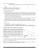
FLUE CONNECTIONS Do not obstruct the flow of flue gases from the flue, located at the rear of the griddle. It is recommended that flue gases be ventilated to the outside of the building through a ventilation system installed by qualified personnel. From the termination of the flue to the filters of the hood venting system, a minimum clearance of 18” must be maintained.
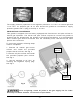
Fig. 2 Fig. 3 The supply pressure (upstream of the regulator) should be 7-9” W.C. for natural gas and 11-12” W.C. for propane gas. At no time should the griddle be connected to supply pressure greater than ½ psig (3.45 kPa) or 14” W.C. PROPANE GAS CONVERSION This griddle is shipped from the factory equipped with fixed burner and pilot orifices for natural gas operation. The burner and pilot orifices required to convert the griddle to propane gas are shipped with the griddle in the shipping packaging.
OPERATION The griddle and its parts are hot. Use care when operating, cleaning or servicing the griddle. BEFORE FIRST USE Remove all packing material and protective plastic from surfaces of the unit. Before leaving the factory, the griddle plate is coated with protective coating as a rust inhibitor. Remove this film when the griddle plate is being cleaned prior to its first cooking use.
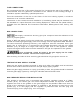
VCRG-T / WCRG-T PILOT LIGHTING PROCEDURE 1. Turn the main gas shut-off valve and all thermostats to the OFF position. Wait 5 minutes to allow any gas that may have accumulated in the burner compartment to escape. 2. Turn the main gas shut-off valve ON. 3. Depress and hold the safety valve button while lighting the corresponding pilot. You will have to reach under the front of the unit to light with an outside ignition source(such as a lit taper, etc.) while viewing thru the pilot sight hole. 4.
USING THE GRIDDLE To preheat, turn the burners on about 20-25 minutes before cooking. A uniform and systematic approach to loading the griddle will produce the most consistent product results. The griddle plate is steel, but the surface can be scored or dented by careless use of a spatula or scraper. Be careful not to dent, scratch, or gouge the plate surface. Do not try to knock off loose food that may be on the spatula by tapping the corner or the edge of the spatula on the griddle surface.
CLEANING THE GRIDDLE Empty the grease drawer as needed throughout the day and regularly clean at least once daily. Clean the griddle regularly. A clean griddle always looks better, lasts longer and performs better. To produce evenly cooked, perfectly browned griddle products keep the griddle plate clean and free of carbonized grease. Carbonized grease on the surface hinders the transfer of heat from the griddle surface to the food, resulting in spotty browning and loss of cooking efficiency.
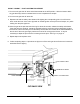
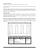
ADJUSTMENTS CALIBRATION 1. Each thermostat controls a 12” zone of the griddle. Using a Surface Probe temperature measurement device, observe the temperatures at the center points of the cooking zones. These points are located by starting 6” from the side splash (left or right) and every 12” across the width of the griddle, with all points located 12” back from the front edge of the griddle plate. NOTE: Use of infrared thermometers is not recommended.
LEVELING The griddle must be level (side-to-side and front-to-back) during operation to ensure proper performance. Improper leveling can result in uneven temperature distribution, cold spots, and possibly damaged components. 1. Place a level on the griddle. 2. Adjust legs by turning the bullet feet at the bottom of each leg. Using pliers or a crescent wrench, turn the feet counter-clockwise to increase height, and clockwise to decrease height until leveling is achieved.
SHUTDOWN OF GRIDDLE 1. Turn thermostats to the OFF position to cut off burners. 2. The pilots will remain lit and monitored by the safety valve as long as the main gas supply is on. EXTENDED SHUTDOWN 1. Shut off the main gas supply valve. 2. Apply a heavy coat of vegetable oil over the griddle plate to inhibit rust. MAINTENANCE The griddle and its parts are hot. Use care when operating, cleaning or servicing the griddle. LUBRICATION There are no parts on this griddle that require lubrication.
TROUBLESHOOTING PROBLEM POSSIBLE CAUSES Burner does not come on when the control knob is turned on 1. Problem with gas valve. (Call for service) 2. Pilot burner not lit. (Call for service) 3. Low gas pressure. (Call for service) Pilot burner will not light 1. 2. 3. 4. Pilot burner will not stay lit 1. Obstructed or wrong size pilot orifice. (Call for service) 2. Gas supply not purged of air. Depress pilot safety button until air is purged. 3. Air blowing pilot out. (Call for service) 4.
MANUEL D’INSTALLATION ET D’EMPLOI Plaque chauffante au gaz à fonction moyenne WCRG48-T VCRG48-T WCRG36-T VCRG36-T WCRG24-T VCRG24-T MODÈLES MODÈLES VCRG48-T ITW Food Equipment Group, LLC 3600 North Point Blvd. Baltimore, MD 21222 GARDER CE MANUAL POUR UNE UTILISATION FUTURE FORMULAIRE F-38305 (rev.
IMPORTANT POUR VOTRE SÉCURITÉ CE MANUEL A ÉTÉ CONÇU POUR LE PERSONNEL APTE À INSTALLER UN ÉQUIPEMENT AU GAZ, QUI DOIT EFFECTUER LA MISE EN MARCHE ET LES RÉGLAGES INITIAUX DE L’ÉQUIPEMENT DONT IL S’AGIT DANS CE MANUEL. PLACEZ DANS UN ENDROIT IMPORTANT LES INSTRUCTIONS QUI DOIVENT ÊTRE SUIVIES AU CAS OÙ UNE ODEUR DE GAZ SERAIT DÉTECTÉE. VOUS POUVEZ DEMANDER CES RENSEIGNEMENTS AU FOURNISSEUR DE GAZ LOCAL.
INSTALLATION, EMPLOI ET ENTRETIEN DES Plaque chauffante à fonction moyenne GENERAL Les plaques chauffantes à fonction moyenne sont produites avec une qualité de l'exécution et des matériaux. L’installation, l’utilisation et l’entretien adéquats de votre plaque chauffante vous apporteront de nombreuses années de performance satisfaisante. Lisez entièrement ce manuel et suivez attentivement toutes les instructions données.
ESPACES À PRÉVOIR DURANT L'INSTALLATION Derrière : Côtés : 0 cm 0 cm 15 cm 15 cm CONSTRUCTION INCOMBUSTIBLE CONSTRUCTION COMBUSTIBLE Cô é ET NORMES D’INSTALLATION CODES La plaque chauffante doit être installée conformément à : Aux États-Unis d'Amérique : National Fuel Gas Code, ANSI-Z223.1/NFPA N o 54 (dernière édition). Cela doit comprendre sans être limité à : NFPA N o 54 Section 10.3.5.2 pour la ventilation.
CONNEXIONS DES CONDUITS Ne pas obstruer la circulation des gaz de combustion provenant des conduits, situés à l’arrière de la plaque chauffante. On recommande que les gaz de combustion soient aspirés à l'extérieur de l'édifice à l'aide d'un système de ventilation installé par du personnel compétent. Un espace minimum de 46 cm doit maintenu à partir de la fin du conduit aux filtres du système de hotte à évacuation.
Fig. 2 Fig. 3 La pression d'alimentation (en amont du régulateur) devrait être de 18 à 23 cm CE pour le gaz naturel et de 28 à 30 cm CE pour le gaz propane. La plaque chauffante ne devrait à aucun moment être connectée à une pression d’alimentation supérieure à ½ psi (3,45 kPa) ou 36 cm CE. CONVERSION DU GAZ PROPANE Cette plaque chauffante est livrée de l’usine munie d'orifices fixes de combustion et de veilleuse d’allumage pour l’emploi du gaz naturel.
EMPLOI La plaque chauffante et ses pièces sont chaudes. Faites attention lorsque vous employez, nettoyez ou entretenez la plaque chauffante. AVANT LA PREMIÈRE UTILISATION Retirez tout le matériel d’emballage et la protection en plastique des surfaces de l’appareil. Avant de quitter l’usine, la plaque chauffante est couverte d’un enduit protecteur en tant qu'antirouille. Retirez cette pellicule lors du nettoyage de la plaque chauffante avant la première utilisation en cuisine.
PROCÉDURE D’ALLUMAGE DE LA VEILLEUSE VCRG-T / WCRG-T 1. Fermez le robinet d’arrêt principal du gaz et tous les thermostats. Attendez 5 minutes pour permettre à tout gaz accumulé dans le compartiment des brûleurs de s’échapper. 2. Ouvrez le robinet d’arrêt principal du gaz. 3. Appuyez et tenez le bouton de la soupape de sûreté pendant l'allumage de la veilleuse correspondante.
UTILISATION LA PLAQUE CHAUFFANTE Pour préchauffer, ouvrez les brûleurs environ 20 à 25 minutes avant la cuisson. Un approche uniforme et méthodique pour remplir la plaque chauffante produira les résultats les plus constants. La plaque est en acier, mais la surface peut être rayée ou bosselée par un mauvais usage d'une spatule ou d’un grattoir. Faites attention de ne pas bosseler, égratigner ou percer la surface de la plaque.
NETTOYAGE LA PLAQUE CHAUFFANTE Videz le tiroir à graisse au besoin tout au long de la journée et le nettoyez régulièrement au moins une fois par jour. Nettoyez régulièrement la plaque chauffante Une plaque chauffante propre a toujours un meilleur aspect, dure plus longtemps et a une meilleure performance. Pour obtenir des aliments cuits de façon uniforme et parfaitement grillés, garder la plaque propre et sans gras carbonisé.
RÉGLAGES CALIBRAGE 1. Chaque thermostat contrôle une zone de 30 cm de la plaque chauffante. À l’aide d’une sonde de surface permettant de mesurer la température, observez les températures aux points centrés de la zone de cuisson. Ces points sont situés en commençant à 15 cm à partir du côté contre les éclaboussures (gauche ou droit) et à chaque 30 cm de la largeur de la plaque, avec tous les points situés à 30 cm à l’arrière de la partie antérieure de la plaque.
MISE À NIVEAU La plaque chauffante doit être mise à niveau (d’un côté à l’autre et du devant vers l’arrière) quand vous l'utilisez pour assurer une performance adéquate. Une mise à niveau inadéquate peut provoquer une répartition de la température inégale, des zones froides et possiblement des composants endommagés. 1. Placez un niveau sur la plaque chauffante. 2. Réglez les pattes en tournant les pieds en bas de chaque patte.
FERMERTURE LA PLAQUE CHAUFFANTE 1. Fermez les thermostats pour éteindre les brûleurs. 2 Les veilleuses resteront allumées et contrôlées par la soupape de sûreté aussi longtemps que l’alimentation principale en gaz est ouverte FERMETURE PROLONGÉE 1. Fermez le robinet principal d’alimentation en gaz. 2. Mettez une généreuse couche d’huile végétale sur la plaque pour empêcher la rouille. ENTRETIEN La plaque chauffante et ses pièces sont chaudes.
PROBLÈME DÉPANNAGE CAUSES POSSIBLES 1. La température est trop haute. 2. La surface de la plaque a besoin d’un nettoyage ou d’un rodage. 3. Il y a trop de gras utilisé sur la plaque Accumulation visible de gomme sur la plaque 1. La nourriture elle-même a un goût altéré. 2. La nourriture a été gardée dans de mauvaises conditions avant la cuisson. 3. Il y a trop de gras utilisé sur la plaque 4. La température est trop basse. La nourriture goûte le gras ou a un goût altéré désagréable 1.