INSTALLATION & OPERATION MANUAL FOR Cheesemelters MODELS MLS VCM24 ML-135124 VCM34 ML-135123 VCM36 ML-135126 VCM48 ML-135127 VCM60 ML-135128 VCM72 ML-135129 www.vulcanhart.com MODELS MLS CMJ24 ML-135124 CMJ34 ML-135123 CMJ36 ML-135126 CMJ48 ML-135127 CMJ60 ML-135128 CMJ72 ML-135129 www.wolfrange.com CMJ36 ITW Food Equipment Group, LLC 3600 North Point Blvd.
IMPORTANT FOR YOUR SAFETY THIS MANUAL HAS BEEN PREPARED FOR PERSONNEL QUALIFIED TO INSTALL GAS EQUIPMENT, WHO SHOULD PERFORM THE INITIAL FIELD START-UP AND ADJUSTMENTS OF THE EQUIPMENT COVERED BY THIS MANUAL. POST IN A PROMINENT LOCATION THE INSTRUCTIONS TO BE FOLLOWED IN THE EVENT THE SMELL OF GAS IS DETECTED. THIS INFORMATION CAN BE OBTAINED FROM THE LOCAL GAS SUPPLIER.
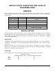
INSTALLATION, OPERATION AND CARE OF CHEESEMELTERS GENERAL Cheesemelters are produced with quality workmanship and material. Proper installation, usage and maintenance of your Cheesemelter will result in many years of satisfactory performance.
The installation location must allow adequate clearances for servicing and proper operation. While another gas-fired cheesemelter can be placed adjacent to this Cheesemelter, there must be no obstruction to the front of the Cheesemelter. A minimum front clearance of 36" (91 cm) is required. Do not obstruct the flow of combustion and ventilation air. Adequate clearance for air openings into the combustion chamber must be provided.
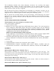
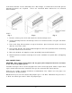
If the Cheesemelter is to be mounted over a Gas Range, a reinforced hi-shelf and special mounting brackets are required. These are furnished when ordered as an elevated Cheesemelter. Fig. 1 Fig. 2 Fig. 3 1. Remove existing rear shelf and install the reinforced high shelf. 2. Install mounting brackets on both top corners of reinforced shelf, using the four bolts provided. 3. Place and align Cheesemelter on top of brackets; place the back of the unit flush with the rear of the shelf. 4.
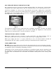
GAS PRESSURE REGULATOR INSTALLATION Gas regulator pressure is preset at 6” Water Column (W.C.) for natural gas, and 10” W.C. for propane gas. Minor adjustments may be required based on site specific gas pressure. Install the regulator as close to the cheesemelter on the gas supply line as possible. Make sure that the arrow on the underside of the regulator is oriented in the direction of gas flow to the cheesemelter (Fig.
OPERATION WARNING: THE CHEESEMELTER AND ITS PARTS ARE HOT. BE CAREFUL WHEN OPERATING, CLEANING OR SERVICING THE CHEESEMELTER. CONTROLS Burner Valve — the burner valve regulates the flow of gas throughout the Cheesemelter. Gas flow is increased by turning the valve counterclockwise. After preheating, the maximum output is not required. Turn the valve clockwise until the desired performance is achieved. Sliding Shelves (Rack) — there are three rack positions.
LOADING AND UNLOADING Place the rack in the desired position. Pull the rack out for loading. Load as quickly as possible and avoid spillage. Push the rack into place and cook for the appropriate time. Lower and pull the rack out for unloading. CLEANING Interior When the Cheesemelter is cool, remove rack. Clean the rack and drip tray daily by soaking in warm detergent water. Scrub with a stiff-bristled brush. Do not use harsh abrasives. After scrubbing, wash with soapy water, rinse and dry.
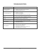
TROUBLESHOOTING PROBLEM POSSIBLE CAUSES Uneven heating Side burning 1. Temperature too low 2. Improper operation of Cheesemelter 3. Fluctuating gas pressure Too much top heat 1. 2. 3. 4. Uneven heat, side to side 1. Cheesemelter not level, side to side 2. Cheesemelter burner improperly installed Uneven heat, front to back Temperature too high Improper ventilation Excessive heat input Pressure too high, or orifice(s) too large Cheesemelter not level, front to back Dried-out products 1.