SERVICE MANUAL VHX BOILER BASE SERIES HIGH EFFICIENCY GAS STEAMERS VHX24G ML-114795 VHX24G5 ML-126590 MHB24G ML-114954 (BASE ONLY) VHX24G SHOWN - NOTICE This Manual is prepared for the use of trained Vulcan Service Technicians and should not be used by those not properly qualified. If you have attended a Vulcan Service School for this product, you may be qualified to perform all the procedures described in this manual. This manual is not intended to be all encompassing.
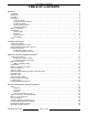
VHX SERIES STEAMERS TABLE OF CONTENTS GENERAL . . . . . . . . . . . . . . . . . . . . . . . . . . . . . . . . . . . . . . . . . . . . . . . . . . . . . . . . . . . . . . . . . . . . . . . . . . . . . Installation . . . . . . . . . . . . . . . . . . . . . . . . . . . . . . . . . . . . . . . . . . . . . . . . . . . . . . . . . . . . . . . . . . . . . . . . . Maintenance . . . . . . . . . . . . . . . . . . . . . . . . . . . . . . . . . . . . . . . . . . . . . . . . . . . . . . . . . . . . . . . . . . . . . .
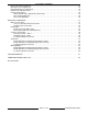
VHX SERIES STEAMERS Air Pressure Switch Adjustment . . . . . . . . . . . . . . . . . . . . . . . . . . . . . . . . . . . . . . . . . . . . . . . . . . . . . . . . Gas Pilot Pressure Adjustment . . . . . . . . . . . . . . . . . . . . . . . . . . . . . . . . . . . . . . . . . . . . . . . . . . . . . . . . . Gas Manifold Pressure Adjustment . . . . . . . . . . . . . . . . . . . . . . . . . . . . . . . . . . . . . . . . . . . . . . . . . . . . . Ignition Control Module Checks . . . . . . . . . . . . . . . . . .
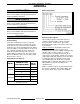
VHX SERIES STEAMERS - GENERAL GENERAL Model Designations INSTALLATION Refer to the Installation and Operation Manual for detailed installation instructions. MAINTENANCE Refer to the Installation and Operation Manual for specific maintenance instructions. CLEANING Refer to the Installation and Operation Manual for specific cleaning instructions.
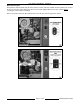
VHX SERIES STEAMERS - GENERAL Boiler Control Styles VHX Steamers manufactured using the old style boiler controls ended on 5/19/00. Steamers that were in stock at the time of the boiler control changeover were removed and equipped with the new style controls without recording the serial number for tracking. Refer to the pictures below to differentiate between the old style and new style boiler controls.
VHX SERIES STEAMERS - GENERAL WATER CONDITIONING SPECIFICATIONS Furnishing the boiler with treated water to reduce scale formation is important. Scale formation will reduce steam output, cause premature component failure, and shorten equipment life. Most water supplies contain scale producing minerals such as Calcium and Magnesium. As steam is generated, the minerals remain and dissolve into the water.
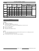
VHX SERIES STEAMERS - GENERAL Gas Supply INPUT (BTU/HR) MODEL NAT. PROP. MANIFOLD PRESSURE (INCHES W.C.) PILOT PRESSURE (INCHES W.C.) LINE PRESSURE (INCHES W.C.) NATURAL PROPANE MINIMUM MINIMUM RECOMMENDED RECOMMENDED NAT. PROP. NAT. PROP. 200,000 200,000 3.0 3.0 3.5 3.5 7.0 11.0 270,000 270,000 3.0 3.0 3.5 3.5 7.0 11.0 200,000 200,000 3.0 3.0 3.5 3.5 7.0 11.0 270,000 270,000 3.0 3.0 3.5 3.5 7.0 11.0 200,000 200,000 3.0 3.0 3.5 3.5 7.0 11.0 270,000 270,000 3.
VHX SERIES STEAMERS - OPERATION STEAMER OPERATION 2) CABINET BASE BOILER Ensure that all utility connections to the steamer have been made and are turned ON and that the knob on the main gas valve is in the ON position. The VHX Series steamers are CSD-1 compliant and are equipped with amber colored lights on the boiler control panel for High Pressure and Low Water level that illuminate and stay on until the boiler is full and the manual reset switch pressed. 1.
VHX SERIES STEAMERS - OPERATION 1. With both timer knobs at the off position, open the compartment doors and observe that no steam has entered the cooking compartments, then close the doors. BOILER BLOWDOWN AND STEAMER SHUT OFF 2. Set both timer knobs at 2 minutes. The ready lights will go off, the cooking lights will come on, and steam will begin to enter the compartments. Turn the steamer off at least once daily to blowdown the boiler.
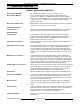
VHX SERIES STEAMERS - COMPONENT FUNCTION COMPONENT FUNCTION CABINET BASE BOILER CONTROLS Power Switch (ON/OFF) . . . . . . . . . When turned ON, supplies power to the control circuit. Reset Switch (Manual) . . . . . . . . . . Resets the low water level safety circuit on initial startup or the occurrence of a low water condition and allows the boiler to fill with water.
VHX SERIES STEAMERS - COMPONENT FUNCTION Relay Board . . . . . . . . . . . . . . . . . . . Provides a centralized location for wire harness connections and power transfer through board relays (K1-K7) to the steamer controls. Also, provides a condition or component troubleshooting indicator by utilizing seventeen LED’S on the board to represent the status of the condition or component in the operation sequence. For an LED legend, see "RELAY BOARD" under "ELECTRICAL OPERATION". New style controls only.
VHX SERIES STEAMERS - COMPONENT FUNCTION COOKING COMPARTMENT CONTROLS The upper section of the steamer consists of two separate cooking compartments. Each compartment functions independently with its own set of controls. Power is supplied to the controls only after the steam pressure rises above the compartment pressure switch setting to close the N.O. contacts. Ready Light (Green) . . . . . . . . . . . . When lit, indicates steamer is ready to cook. Cooking Light (Red) . . . . . . . . . . . .
VHX SERIES STEAMERS - REMOVAL AND REPLACEMENT OF PARTS REMOVAL AND REPLACEMENT OF PARTS COMPONENT LOCATIONS Cabinet Base Boiler Controls Page 13 of 68 F24700 (October 2001)
VHX SERIES STEAMERS - REMOVAL AND REPLACEMENT OF PARTS Cabinet Base Boiler Controls Continued F24700 (October 2001) Page 14 of 68
VHX SERIES STEAMERS - REMOVAL AND REPLACEMENT OF PARTS Cooking Compartment Controls WATER LEVEL CONTROLS (MAIN OR AUXILIARY LLCO) RELAY BOARD WARNING: DISCONNECT THE ELECTRICAL POWER TO THE MACHINE AT THE MAIN CIRCUIT BOX. PLACE A TAG ON THE CIRCUIT BOX INDICATING THE CIRCUIT IS BEING SERVICED. 1. Open the cabinet base door. 2. Remove the cover from the pressure switch control box to access the water level controls.
VHX SERIES STEAMERS - REMOVAL AND REPLACEMENT OF PARTS 1) WATER LEVEL GAUGE ASSEMBLY WARNING: DISCONNECT THE ELECTRICAL POWER TO THE MACHINE AT THE MAIN CIRCUIT BOX. PLACE A TAG ON THE CIRCUIT BOX INDICATING THE CIRCUIT IS BEING SERVICED. 1. Open the cabinet base door and remove the right side panel. 2. Close the valve at the top and at the bottom of the gauge assembly. 3. Unscrew the packing nuts at the top and bottom of the glass tube. 4. B.
VHX SERIES STEAMERS - REMOVAL AND REPLACEMENT OF PARTS a. B. 6. From the bottom right side, raise the boiler two to three inches so it tilts to the left. When the remaining water has drained out, lower the boiler before. proceeding. Remove the drain/scale clean-out plug from the bottom of the boiler. Slide the boiler forward and remove it from base frame. 7. Install a new boiler and secure it to frame. 8. Refer to "HEAT EXCHANGER" and perform steps 13 through 15. 9.
VHX SERIES STEAMERS - REMOVAL AND REPLACEMENT OF PARTS BURNER HEAD ASSEMBLY WARNING: DISCONNECT THE ELECTRICAL POWER TO THE MACHINE AT THE MAIN CIRCUIT BOX. PLACE A TAG ON THE CIRCUIT BOX INDICATING THE CIRCUIT IS BEING SERVICED. WARNING: SHUT OFF THE GAS SUPPLY BEFORE SERVICING THE UNIT. 1. Remove the pressure gauge tubing and power cable from the rear of the control panel then remove the panel. 2. Disconnect the spark ignition cable from the ignitor terminal. 3.
VHX SERIES STEAMERS - REMOVAL AND REPLACEMENT OF PARTS NOTE: Removal of the gas valve piping assembly assumes the use of a gas line quick connect or union at the gas supply inlet to the steamer. HEAT EXCHANGER WARNING: SHUT OFF THE GAS BEFORE SERVICING THE UNIT. 8. Remove the four nuts from combustion blower mounting flange and remove blower from burner tube assembly. 9. Remove the four bolts connecting the horizontal flue (left of boiler) to the flue "transition" piece.
VHX SERIES STEAMERS - REMOVAL AND REPLACEMENT OF PARTS 12. For clearance of the heat exchanger only, remove the drain nut (petcock) and the lower adjustment knob from the water level gauge. A. 13. To install heat exchanger: Remove the remaining bolts on the heat exchanger then pull heat exchanger straight out from the boiler. F24700 (October 2001) Page 20 of 68 A. Clean the mating surfaces on the heat exchanger and boiler. B. Install a new gasket on the boiler side of the mounting flange. C.
VHX SERIES STEAMERS - REMOVAL AND REPLACEMENT OF PARTS NOTE: It may be necessary to use two clamps to draw the bottom of the heat exchanger close enough to be clamped. Start one clamp at a 3 o’clock position then install other clamp near the bottom. Once the bolts are tight enough, CClamp will fall away. E. Install two bolts at the bottom and two bolts at the top on the heat exchanger flange and tighten the bolts a few turns at a time.
VHX SERIES STEAMERS - REMOVAL AND REPLACEMENT OF PARTS NOTE: When installing the spacers, the smaller diameter fits into the slot in the door and the latch lever must rest on top of the handle latch screw. 5. Reverse procedure to install. Latch Assembly Handle 1. Open the door. 2. Remove screws from the top and bottom of the door. 3. Pull the inner door panel out from the door housing with the gasket plate and gasket still attached. 1. Open the door. 2.
VHX SERIES STEAMER - SERVICE PROCEDURES AND ADJUSTMENTS SERVICE PROCEDURES AND ADJUSTMENTS WARNING: CERTAIN PROCEDURES IN THIS SECTION REQUIRES ELECTRICAL TEST OR MEASUREMENTS WHILE POWER IS APPLIED TO THE MACHINE. EXERCISE EXTREME CAUTION AT ALL TIMES. IF TEST POINTS ARE NOT EASILY ACCESSIBLE, DISCONNECT POWER, ATTACH TEST EQUIPMENT AND REAPPLY POWER TO TEST. A.
VHX SERIES STEAMER - SERVICE PROCEDURES AND ADJUSTMENTS WARNING: READ AND FOLLOW THE INSTRUCTIONS FOR THE DE-LIMING CHEMICAL BEING USED. USE PLASTIC OR RUBBER GLOVES TO AVOID SKIN CONTACT. IF THE CHEMICAL COMES IN CONTACT WITH SKIN, RINSE WITH CLEAN WATER. 5. Mix deliming solution according to the instructions for the chemical being used. NOTE: Boiler water capacity is approximately seven gallons. NOTE: If deliming solution comes in contact with steamer components, lightly rinse off with clean water. A.
VHX SERIES STEAMER - SERVICE PROCEDURES AND ADJUSTMENTS used, a frequent interval should be used. This blowdown procedure is essential to proper operation and component life by removing sediment and scalants that may be lodged in the probe housing. NOTE: Boiler should be within normal operating pressures. should be inspected. WARNING: THE FOLLOWING STEPS REQUIRE POWER TO BE APPLIED TO THE UNIT DURING THE TEST. USE EXTREME CAUTION AT ALL TIMES. Main Water Level Control 1.
VHX SERIES STEAMER - SERVICE PROCEDURES AND ADJUSTMENTS C. 3. Verify LED’s on the water level control board, HL LED should be off, and LLCO LED should be illuminated. Open the ball valve in the probe housing assembly (boiler left side) about half way, to gradually remove boiler water and activate a fill cycle. Do not press the reset switch to start the ignition cycle. The next step requires a visual sight glass measurement that cannot be obtained, if there is boiling action in the vessel. A. C.
VHX SERIES STEAMER - SERVICE PROCEDURES AND ADJUSTMENTS boiler shell, remove and clean the Aux LLCO probe. a. b. 4. Replace the probe and check resistance again. If resistance is still present, install a new probe. Replace lead wire on probe and repeat steps "2) thru 4)" to verify proper operation. PRESSURE SWITCHES WARNING: THE FOLLOWING STEPS REQUIRE POWER TO BE APPLIED TO THE UNIT DURING THE TEST. USE EXTREME CAUTION AT ALL TIMES.
VHX SERIES STEAMER - SERVICE PROCEDURES AND ADJUSTMENTS Mechanical Pressure relief valve factory set to approximately 15 PSI. If the pressure in the boiler reaches this level, the valve will OPEN. A. FILL AND COLD WATER SOLENOID VALVES High pressure light (amber) will come ON. 1) If the pressure switch opens at a pressure range other than 14.5 to 15.0 PSI then an adjustment to the switch setting should be made. a. Proceed to step 5.
VHX SERIES STEAMER - SERVICE PROCEDURES AND ADJUSTMENTS D. 9. Check ports in valve body. A. If the boiler blowdown is ok, then the drain line and valve are clear of debris and the valve is functioning properly. B. If considerable lime scale debris is apparent, then not only the blowdown valve, but also the boiler and water level probes must be thoroughly cleaned.
VHX SERIES STEAMER - SERVICE PROCEDURES AND ADJUSTMENTS MAIN BURNER IGNITION CHECKS The complete gas burner assembly is located inside the heat exchanger casting in the boiler. The perforated burner head functions as both pilot and main gas burner. The inner portion of the perforated burner head serves as the pilot to light the main burner during the trial for ignition. Once the main burner lights, the flame encompasses the entire perforated burner head and the pilot flame extinguishes.
VHX SERIES STEAMER - SERVICE PROCEDURES AND ADJUSTMENTS 5) a. If ignitor sparks and pilot lights, proceed to step 7. Verify the burner tube insulation and heat exchanger casting are intact. b. If ignitor does not spark, proceed to step "5)" below. NOTE: The suggested method for inspection is to mount a small mirror to a 2 foot long rod and insert the mirror inside the burner tube and use a flashlight to illuminate the area.
VHX SERIES STEAMER - SERVICE PROCEDURES AND ADJUSTMENTS F24700 (October 2001) Page 32 of 68
VHX SERIES STEAMER - SERVICE PROCEDURES AND ADJUSTMENTS AIR PRESSURE SWITCH ADJUSTMENT The air pressure switch senses the pressure level produced by the blower for combustion. When the pressure is sufficient, the switch closes and supplies power to the ignition control module. The gas ignition sequence starts to light the gas pilot and then main burner.
VHX SERIES STEAMER - SERVICE PROCEDURES AND ADJUSTMENTS 2) C. Press the reset switch to start the ignition process. Listen for main gas burner ignition to verify operation. GAS PILOT PRESSURE ADJUSTMENT WARNING: DISCONNECT THE ELECTRICAL POWER TO THE MACHINE AT THE MAIN CIRCUIT BOX. PLACE A TAG ON THE CIRCUIT BOX INDICATING THE CIRCUIT IS BEING SERVICED. WARNING: SHUT OFF THE GAS BEFORE SERVICING THE UNIT. 5. c. Replace the orifice, pressure switch and connect the lead wires to the switch.
VHX SERIES STEAMER - SERVICE PROCEDURES AND ADJUSTMENTS 4. After the main burner lights, allow the boiler to reach operating pressure then turn the ON/OFF knob for the main gas valve to OFF. 5. Restart the ignition sequence by "rapidly" turning the power switch OFF then back ON. A rapid switching is needed to keep the boiler from starting automatic blowdown. A. 6. With the burner lit, set the pressure as outlined below. Press the reset switch to start the ignition process.
VHX SERIES STEAMER - SERVICE PROCEDURES AND ADJUSTMENTS A. GAS MANIFOLD PRESSURE ADJUSTMENT WARNING: DISCONNECT THE ELECTRICAL POWER TO THE MACHINE AT THE MAIN CIRCUIT BOX. PLACE A TAG ON THE CIRCUIT BOX INDICATING THE CIRCUIT IS BEING SERVICED. NOTE: The gas supply line to the steamer should be a minimum of one inch diameter (ID). WARNING: SHUT OFF THE GAS SUPPLY BEFORE SERVICING THE UNIT. B. 1. Open the cabinet base door to access main gas valve. 2.
VHX SERIES STEAMER - SERVICE PROCEDURES AND ADJUSTMENTS 7. Once the correct pressure has been set, turn the gas supply and power switch OFF. Replace the adjustment screw cap and manifold pressure plug tap plug on the valve. F. 8. Turn the gas supply on and check for proper operation. NOTE: If the power is not re-set, the ignition module continues sparking for a total of 90 seconds, then locks out.
VHX SERIES STEAMER - SERVICE PROCEDURES AND ADJUSTMENTS Spark Verification Test 1. Turn the power switch OFF. 2. Check to ensure that all electrical terminal connections on the ignition control module and the ignitor rod are clean and tight. If the ignition cable appears to be damaged, replace it and re-try lighting burner. 3. 2) If ignitor does not spark, repeat steps E thru this step until rod has been rotated 360°. 3) If ignitor still does not spark, proceed to step 6.
VHX SERIES STEAMER - SERVICE PROCEDURES AND ADJUSTMENTS Door Sealing Adjustment COOKING COMPARTMENT 1. Check the door gasket quality. If damaged or worn, replace as outlined in "REMOVAL" under "COOKING COMPARTMENT DOOR(S)". 2. Loosen screws until the screw heads no longer touch the gasket plate. 3. Tighten screws until screw head touches gasket plate and at that point begin counting turns. 4. Tighten all screws approximately two turns. 5. Close the door and check for proper operation.
VHX SERIES STEAMER - ELECTRICAL OPERATION Door Latch Adjustment Should the cooker door jam and can not be opened, DO NOT FORCE OR PRY the door as damage will occur. First, try lifting up on the bottom of the door at the handle end to disengage the latch. If that does not work, remove the right side panel. The striker that catches on the door latch is located behind the front face of the cooking cavity. Remove the nut from the striker and this will release it from the panel. 4.
VHX SERIES STEAMER - ELECTRICAL OPERATION ELECTRICAL OPERATION into the boiler. WATER LEVEL CONTROLS Low Level Cut-Off & Differential Control The steamer is equipped with three water level sensing probes (high, low and low level cut-off) and a single water level control board (solid state). The water level control board performs two functions: 1) Provide low level cut-off protection to shut off the heat source in case the water level drops below the low level cut-off (LLCO) probe.
VHX SERIES STEAMER - ELECTRICAL OPERATION Auxiliary Low Level Cut-Off This control serves as a safety backup to the main water level control (WLC) board to meet CSD-1 code requirements. The operation of the auxiliary control is identical to the low level cut-off (LLCO) function of the main WLC board but performs a single function: 1) Provide auxiliary low level cut-off protection to shut off the heat source in case the water level drops below the low level cut-off (LLCO) probe.
VHX SERIES STEAMER - ELECTRICAL OPERATION RELAY BOARD Board Layout and LED Legend The relay board Provides a centralized location for wire harness connections and power transfer through board relays (K1-K7) to the other steamer controls. Also, provides a condition or component troubleshooting indicator by utilizing seventeen LED’S on the board to represent the status of the condition or component in the operating sequence.
VHX SERIES STEAMER - ELECTRICAL OPERATION Boiler Operational Status (LED Indicator) Use the tables below to determine the operational status of a component or condition by utilizing the LED indicators on the board. The operational state’s are divided into categories A thru F.
VHX SERIES STEAMER - ELECTRICAL OPERATION LED STATUS ON DESCRIPTION OFF ELECTRICAL COMPONENTS CONDITION N1 X same as “state A” N2 X same as "state B" N3 X same as “state A” N4 X same as "state B N5 X Reset switch is/was momentarily energized K3 energized - K3(1) CLOSE (locking circuit) Aux Water level is satisfied. (Amber WATER light OFF) K3 energized - K3(1) OPEN Reset switch is/was momentarily energized K4 energized - K4(1) CLOSE (locking circuit) High Limit is satisfied.
VHX SERIES STEAMER - ELECTRICAL OPERATION limit pressure switch contacts (N.C.). SEQUENCE OF OPERATION a. NEW STYLE CONTROLS - BOILER This sequence of operation is written for boiler bases with the new style boiler controls. See "BOILER CONTROL STYLES" under "GENERAL". Refer to schematic diagram TSP1480. 3) 3. Initial Fill and Preheat Conditions. Power switch OFF. B. Boiler connected to correct voltage (120VAC). LLCO relay on water level board energizes, LLCO contacts (N.O.) close 1) B.
VHX SERIES STEAMER - ELECTRICAL OPERATION N11 lit. K4(2) N.O. contacts close. pilot, quickly cycle the reset switch to prevent the boiler from draining. If the pilot is not established within 90 seconds from the ignitor module being energized, the ignition module locks out power to the gas valves. The module remains locked out until the power switch is turned to OFF then ON and the manual reset switch is pressed to r e-start the ignition trial cycle. 1) D.
VHX SERIES STEAMER - ELECTRICAL OPERATION upper and lower set point limits. The cycling pressure switch continues to energize and de-energize the heating circuit to cycle the burner ON and OFF. B. Boiler connected to correct voltage (120VAC). 1) This sequence continues until one of the following occurs: 1) Power switch is turned OFF. 2) Boiler water level drops below the LLCO probes for the main water level control (WLC) and the auxiliary low level control.
VHX SERIES STEAMER - ELECTRICAL OPERATION 3. Water level reaches LLCO (low water level cutoff) probe for the water level control and to the auxiliary LLCO probe for the auxiliary low level cut-off control. A. 3) a. LLCO relay energizes, LLCO contacts (N.O.) CLOSE and LED lights. Aux. LLCO relay energizes, LLCO contacts (N.O.) CLOSE and LED lights. NOTE: The LLCO and aux.
VHX SERIES STEAMER - ELECTRICAL OPERATION upper and lower set point limits. The cycling pressure switch continues to energize and de-energize the heating circuit to cycle the burner ON and OFF. 1) 3. This sequence continues until one of the following occurs: 1) Power switch is turned OFF. 2) Boiler water level drops below the LLCO probes for the main water level control and the auxiliary low level cutoff control 3) Boiler pressurizes to 15 PSI, causing the high limit pressure switch to OPEN.
VHX SERIES STEAMER - ELECTRICAL OPERATION - THIS PAGE INTENTIONALLY LEFT BLANK - Page 51 of 68 F24700 (October 2001)
VHX SERIES STEAMER - ELECTRICAL OPERATION SCHEMATICS Models Built After 5/25/00 (New Style Boiler Controls) F24700 (October 2001) Page 52 of 68
VHX SERIES STEAMER - ELECTRICAL OPERATION Page 53 of 68 F24700 (October 2001)
VHX SERIES STEAMER - ELECTRICAL OPERATION Models Built Before 5/25/00 (Old Style Boiler Controls) F24700 (October 2001) Page 54 of 68
VHX SERIES STEAMER - ELECTRICAL OPERATION Cooking Compartment Controls Page 55 of 68 F24700 (October 2001)
VHX SERIES STEAMER - ELECTRICAL OPERATION WIRING DIAGRAMS Models Built After 5/25/00 (New Style Boiler Controls) F24700 (October 2001) Page 56 of 68
VHX SERIES STEAMER - ELECTRICAL OPERATION Page 57 of 68 F24700 (October 2001)
VHX SERIES STEAMER - ELECTRICAL OPERATION Models Built Before 5/25/00 (Old Style Boiler Controls) F24700 (October 2001) Page 58 of 68
VHX SERIES STEAMER - ELECTRICAL OPERATION Page 59 of 68 F24700 (October 2001)
VHX SERIES STEAMER - ELECTRICAL OPERATION Cooking Compartment Controls F24700 (October 2001) Page 60 of 68
VHX SERIES STEAMER - TROUBLESHOOTING TROUBLESHOOTING BOILER BASE CONTROLS WARNING: CERTAIN PROCEDURES IN THIS SECTION REQUIRE ELECTRICAL TESTS OR MEASUREMENTS WHILE POWER IS APPLIED TO THE MACHINE. EXERCISE EXTREME CAUTION AT ALL TIMES. IF TEST POINTS ARE NOT EASILY ACCESSIBLE, DISCONNECT POWER, ATTACH TEST EQUIPMENT AND REAPPLY POWER TO TEST.
VHX SERIES STEAMER - TROUBLESHOOTING SYMPTOM POSSIBLE CAUSES Blower operating, no pilot gas flow. 1. Main gas supply turned OFF. 2. Ignition module lockout. Turn power switch OFF for several seconds then ON to reset the module. 3. Air pressure switch: A. Not mounted in true vertical position. B. Incorrect pressure setting. C. Malfunctioning switch. 4. Malfunctioning Ignition module. 5. Malfunctioning pilot gas valve. 6. Blocked or dirty pilot gas orifice. Pilot flame not proving or lighting main burner.
VHX SERIES STEAMER - TROUBLESHOOTING SYMPTOM POSSIBLE CAUSES Gas odor. 1. Leaks in pipe fitting connections or components. 2. Leaking pressure tap plug on pilot or main gas valve; loose or missing pressure adjustment screw cap on main gas valve. 3. Leaking gaskets in air/gas mixture path. 4. Pilot or main gas valve malfunction (improper venting or vent blocked). 5. Incorrect gas pressure. 6. Malfunctioning gas burner. 7. Blocked or dirty air orifice on blower. 8. Blocked or dirty gas orifice. 9.
VHX SERIES STEAMER - TROUBLESHOOTING SYMPTOM POSSIBLE CAUSES Boiler Slow to Pressurize (over 15 min. to achieve operating pressure) 1. Low water supply pressure, inline water strainer clogged or fill solenoid valve malfunction. See "INLINE WATER STRAINER CLEANING" and "FILL AND COLD WATER SOLENOID VALVES" in "SERVICE PROCEDURES AND ADJUSTMENTS". 2. Boiler blowdown solenoid valve clogged and not fully closing. Check for a slow leak out of steamer drain. If not able to verify, then proceed to step 3.
VHX SERIES STEAMER - TROUBLESHOOTING SYMPTOM POSSIBLE CAUSES Steam output low or slow cooking. 1. Cooking Compartment. A. Blocked steam injector ports. (Open door, press door switch button and verify good steam flow into compartment). B. Steam solenoid valve not fully opening or blocked. C. Steam intake shut-off valve closed or out of adjustment. See "INTAKE SHUT-OFF VALVE ADJUSTMENT (STEAM FLOW)" in "SERVICE PROCEDURES AND ADJUSTMENTS". 2. Boiler Base. A.
VHX SERIES STEAMER - TROUBLESHOOTING COOKING COMPARTMENT CONTROLS SYMPTOM POSSIBLE CAUSES Cooking compartments do not operate. 1. No power to compartments. 2. Pressure in boiler is below compartment pressure switch setting. 3. Door switch malfunction. 4. Timer malfunction. 5. Malfunctioning pressure switch in compartment. 6. Verify correct compartment wiring and functioning components. Steam generated inside compartment when timer is off. 1. Steam supply solenoid not fully closing (clogged or dirty).
VHX SERIES STEAMER - NOTES - Page 67 of 68 F24700 (October 2001)
VHX SERIES STEAMER - CONDENSED SPARE PARTS LIST CONDENSED SPARE PARTS LIST NEW STYLE CONTROLS ONLY VHX24G, VHX24G5, MHB24G PART NUMBER DESCRIPTION 853582-1 Igniter, Sensor 850778-1 Switch, Air Pressure 850735-1 Blower, Combustion 354344-4 Valve, Pilot Gas 851315-1 Valve, Main Gas 851316-1 Valve, Pressure Relief 13 psi 880413 Valve, Pressure Relief 15 psi 817222 Valve(s), Cold Water Condenser and Boiler Fill 833488 Switch, Pressure Cycling 851578-1 Switch, Pressure High Limit 844062-1