INSTALLATION & OPERATION MANUAL MHB24G MODULAR GAS STEAM BOILER MODEL MHB24G ML-114954 Model MHB24G VULCAN-HART COMPANY, FORM 31181 (Apr. 2001) P.O. BOX 696, LOUISVILLE, KY 40201-0696, TEL. (502) 778-2791 www.vulcanhart.
IMPORTANT FOR YOUR SAFETY THIS MANUAL HAS BEEN PREPARED FOR PERSONNEL QUALIFIED TO INSTALL GAS EQUIPMENT, WHO SHOULD PERFORM THE INITIAL FIELD START-UP AND ADJUSTMENTS OF THE EQUIPMENT COVERED BY THIS MANUAL. POST IN A PROMINENT LOCATION THE INSTRUCTIONS TO BE FOLLOWED IN THE EVENT THE SMELL OF GAS IS DETECTED. THIS INFORMATION CAN BE OBTAINED FROM THE LOCAL GAS SUPPLIER.
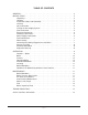
TABLE OF CONTENTS GENERAL . . . . . . . . . . . . . . . . . . . . . . . . . . . . . . . . . . . . . . . . . . . . . . . . . . . . . . . . . . . . 4 INSTALLATION . . . . . . . . . . . . . . . . . . . . . . . . . . . . . . . . . . . . . . . . . . . . . . . . . . . . . . . Unpacking . . . . . . . . . . . . . . . . . . . . . . . . . . . . . . . . . . . . . . . . . . . . . . . . . . . . . . . Location . . . . . . . . . . . . . . . . . . . . . . . . . . . . . . . . . . . . . . . . . . . . . . . . . . . . . . . .
Installation, Operation, and Care of MODEL MHB24G MODULAR GAS STEAM BOILER KEEP THIS MANUAL FOR FUTURE USE GENERAL Vulcan gas steam boilers are produced with quality workmanship and material. Proper installation, usage, and maintenance of your boiler will result in many years of satisfactory performance. It is suggested that you thoroughly read this entire manual and carefully follow all of the instructions provided.
INSTALLATION CODES AND STANDARDS In the United States, the Vulcan gas steam boiler must be installed in accordance with: 1) State and local codes; 2) National Fuel Gas Code, ANSI-Z223.1 (latest edition), available from American Gas Association, 1515 Wilson Boulevard, Arlington, VA 22209; 3) NFPA-96, Vapor Removal from Cooking Equipment; and 4) National Electrical Code, NFPA-70 (latest edition), available from National Fire Protection Association, Batterymarch Park, Quincy, MA 02269.
FLUE CONNECTION DO NOT obstruct the flow of flue gases from the flue located on the rear of the gas steam boiler. It is recommended that the flue gases be ventilated to the outside of the building through a ventilation system installed by qualified personnel. A minimum clearance of 18" (45.7 cm) must be maintained from the termination of the flue to the filters of the hood venting system.
Drain Connection The 11/4" NPT (3.175 cm) threaded fitting on the condenser box must be extended to an open, air gap type drain, with maximum length of 12 inches (30.5 cm) to the open drain. Do not reduce the 11/4" (3.175 cm) drain piping throughout its length. Provide a suitable floor sink with a minimum depth of 12 inches (30.5 cm). The floor sink is NOT to be directly under the boiler and should be at a distance so that steam vapors will not enter the boiler from underneath.
START-UP TEST RUN Refer to the OPERATION section, pages 9 – 11 for more information. WARNING: THE GAS STEAM BOILER AND ITS PARTS ARE HOT. CLEANING, OR SERVICING THE BOILER. USE CARE WHEN OPERATING, After the gas steam boiler is installed and proper service connections have been made, thoroughly test the boiler before operation. 1. Turn knob of gas valve counterclockwise to on. 2. Be sure the water inlet valve is open. Close only for service or long shutdown. 3.
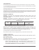
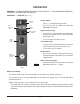
OPERATION WARNING: THE GAS STEAM BOILER AND ITS PARTS ARE HOT. CLEANING, OR SERVICING THE BOILER. USE CARE WHEN OPERATING, CONTROLS — BOILER (Figs. 2, 3) Power Switch POWER SWITCH HIGH PRESSURE LIGHT • Press [ I ] to begin filling the boiler. • Press [ 0 ] to turn the boiler off (automatic blow down will occur). LOW WATER LIGHT High Pressure Light RESET SWITCH (GREEN) • Is lit after [ I ] is pressed and stays on during fill. Goes off after reset switch is pressed (when green light is lit).
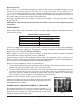
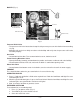
BOILER (Fig. 3) PRESSURE RELIEF VALVE GAS VALVE PROBE HOUSING BLOWDOWN VALVE WATER INLET VALVE MANUAL VALVES WATER LEVEL GAUGE Fig. 3 PL-41514-1 Pressure Relief Valve • The pressure relief valve located on the top left side prevents pressure in the boiler from exceeding 15 psig. • Manually pull up the lever daily to reduce scale buildup and verify that the pressure relief valve functions properly. Gas Valve • Located behind the door. Turn counterclockwise to on; clockwise to off.
CLEANING Boiler Blowdown To prevent malfunction of controls and clogging, it is essential to flush (blow down) the boiler every day. This will flush out any accumulated minerals (left from the feed water) and aid in preventing internal scale build-up which, in time, would interfere with proper boiler operation. Failure to blow down the boiler every day may void the warranty applying to the controls.
SCALE RELATED MAINTENANCE Periodic maintenance is necessary to keep your boiler clean and efficient. It is recommended that initially after three months of boiler usage you have your Vulcan Hart authorized servicer inspect the boiler and perform the below listed maintenance and inspections. Local water conditions and steamer usage will determine the frequency that this service must be repeated; however, a minimum recommendation is once a year. This maintenance is not covered by warranty.