OPERATING, INSTALLATION, SERVICE & PARTS MANUAL FOR ELECTRIC RESTAURANT RANGES MODELS: E-36 SERIES & E-60 SERIES VULCAN-HART COMPANY, P.O. BOX 696, LOUISVILLE, KY 40201-0696, TEL.
IMPORTANT OPERATING, INSTALLATION AND SERVICE PERSONNEL Operating information for this equipment has been prepared for use by qualified and/or authorized operating personnel. All installation and service on this equipment is to be performed by qualified, certified, licensed and/or authorized installation or service personnel, with the exception of any marked with a ? in front of the part number.
IMPORTANT NOTES FOR ALL VULCAN APPLIANCES 1. These units are produced with the best possible workmanship and material. Proper installation is vital if best performance and appearance are to be achieved. Installer must follow the installation instructions carefully. 2. Information on the construction and installation of ventilating hoods may be obtained from the "Standard for the installation of equipment for the removal of smoke and grease laden vapors from commercial cooking equipment," NFPA No.
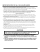
WARNING: DO NOT SPRAY LIQUIDS OR VAPORS ON OR NEAR EQUIPMENT UTILIZING ELECTRICITY CAUTION From the termination of the appliance flue vent to the filters of the hood venting system, an 18 inch minimum clearance must be maintained. Reference: ANSI/NFPA 96-1984 4-1.2.2.2. of the National Fire Protection Association, Inc., Batterymarch Park, Quincy, MA 02269, and National Building Code 1976 Sec. 1015.7b (2) of The American Insurance Association.
ELECTRIC RESTAURANT RANGES Your Vulcan Electric Range is produced with the best possible workmanship and materials. Proper usage and maintenance will result in many years of satisfactory performance. INDEX The manufacturer suggests that you thoroughly read this entire manual and carefully follow all of the instructions provided. Retain this manual for future use.
INSTALLATION INSTRUCTIONS GENERAL INSTALLATION NOTES: The area around units should be kept free and clear of all combustible materials. All units should be positioned for easy accessibility of servicing. All required wiring diagrams are located in the back section of this manual. Vulcan's Restaurant Ranges are U.L listed under File No. E75870 and are for use on electric service of the characteristics specified on the name plate.
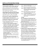
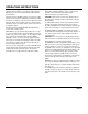
INSTALLATION INSTRUCTIONS Step No. 5 Assemble heat shield to splasher back per detail C — top edge of heat shield must be placed inside the rear top flange of the splasher back.
OPERATING INSTRUCTIONS THEORY OF OPERATION These highly versatile medium duty electric ranges have been engineered and built to give years of satisfactory use. Vulcan Electric Restaurant Ranges are designed for nursing homes, plant cafeterias, churches, schools, restaurants, etc., normally preparing foods in quantities of 50 servings or less. Range is NOT designed for heavy duty application. 1.
OPERATING INSTRUCTIONS OVENS E-36 Model Ranges have a single oven. E-60 Model Ranges have two separate ovens. Each oven is of the semi-directional type. Each oven is equipped with top and bottom heating elements and the top element is controlled by an infinite heat switch. Each oven is controlled by 150° to 550°F thermostat with a red signal light mounted adjacent to the control dial. Each oven has a total input of 5000 W, 1250 W for the top element and 3750 W for the bottom element.
OPERATING INSTRUCTIONS BROILER (Accessory) The broiler, when provided, is of the High shelf type. E60-B or E60-FB ranges also have a 24" double high shelf mounted to the left of broiler. The broiler has two 3000 Watt elements (one left and one right side). Each side (element) is individually controlled by an infinite heat switch. The switches are located on the switch panel at the right of the broiler.
TROUBLE SHOOTING The following is intended to provide a guide for trouble shooting procedure and covers some of the more common problems with the equipment. As with any other equipment, the servicing personnel working on this equipment need to become familiar enough with the circuit and the components in order to be able to follow a logical sequence of trouble shooting and to repair malfunctions not mentioned in the following paragraphs. The instruments necessary for trouble shooting: A. A.C.
TROUBLE SHOOTING (Continued) PROBLEM CORRECTIVE ACTION A top round element is not working. Measure voltage between HI & H2 terminals of the infinite switch. (With switch in HI position) If 208 volt, check for defective element or their connecting leads. If no volt, check the voltage between L1 & L2 terminals of the same switch. If 208 volt, the switch is defective. If no volt, check for bad supply connection to the L1 & L2 terminal. A griddle element is not working.
TROUBLE SHOOTING (Continued) E-36 & E-36-F MODELS PROBLEM CORRECTIVE ACTION The range is completely dead. Check the main disconnect switch & the supply leads. No heat in the oven, but top surface elements are working. Check voltage between leads #9 & 7 on breaker terminal. If no volt, the breaker (or breakers) is either off or defective. If no volt, check for main supply power and connections. If 208 volt, check voltage between #9 & 12 on the thermostat.
PARTS DESCRIPTION & REPLACEMENT WARNING: Turn the main disconnect switch to "off" before servicing the equipment. Reconnect the leads to the replaced component exactly as to the original (refer to the wiring diagrams for each model). A. Switch Panel - see pages 15 & 16 Item 1 - Infinite switch. A DPST cycling switch varies, according to its setting, the percent on-time of the output as shown below.
REPLACEMENT PARTS LIST SWITCH PANEL ASSEMBLY 208 OR 240 VOLT USED ON E-36 SERIES WITH OR WITHOUT SUFFIX "B" ITEM NO. DESCRIPTION 1 Infinite Switch 2 Switch Knob 3 Thermostat 4 Thermostat Knob 5 6 Indicator Light (oven) Switch Panel Assembly Switch Panel Assembly (S/S) * Effective on models constructed after 06/73 ** Effective on models constructed after 1975-77 S/S — Stainless Steel 112674-15 PART NO.
REPLACEMENT PARTS LIST (Continued) SWITCH PANEL ASSEMBLY 208 OR 240 VOLT USED ON E-36F SERIES WITH OR WITHOUT SUFFIX "B" ITEM NO. DESCRIPTION PART NO.
REPLACEMENT PARTS LIST (Continued) SWITCH PANEL ASSEMBLY 208 OR 240 VOLT USED ON E-60 SERIES WITH OR WITHOUT SUFFIX "B" ITEM NO.
REPLACEMENT PARTS LIST (Continued) SWITCH PANEL ASSEMBLY 208 OR 240 VOLT USED ON E-60F SERIES WITH OR WITHOUT SUFFIX "B" ITEM NO. DESCRIPTION PART NO.
REPLACEMENT PARTS LIST (Continued) CONNECTION BLOCK ASSEMBLY 208 OR 240 VOLT USED ON E-36 SERIES WITH OR WITHOUT SUFFIX "F" OR "B" ITEM DESCRIPTION QUANTITY 1 Terminal Block * 110472-8 1 2 Porcelain Block 417934-G1 1 3 Ground Lug 3-1500/06089 1 4 Control Housing Assembly 109469-G1 1 * Effective on models constructed after 4/72 112674-19 PART NO.
REPLACEMENT PARTS LIST (Continued) CONNECTION BLOCK ASSEMBLY 208 OR 240 VOLT USED ON E-60 SERIES WITH OR WITHOUT SUFFIX "F" OR "B" ITEM NO. DESCRIPTION PART NO.
REPLACEMENT PARTS LIST (Continued) 24" FRY PLATE ASSEMBLY 208 OR 240 VOLT USED ON E-60F & E-36F SERIES WITH OR WITHOUT SUFFIX "B" ITEM NO. 1 DESCRIPTION PART NO.
REPLACEMENT PARTS LIST (Continued) FRENCH PLATE ASSEMBLY 208 OR 240 VOLT USED ON MODELS: E-36 & E-60 ITEM NO. DESCRIPTION QUANTITY E-60 E-36 1 Surface Element Plate 107642-1 10 6 2 Surface Element Cover 24153-1 10 6 3 Element (208 Volt) *110911-1 10 6 *110911-2 10 6 107791-G1 10 6 3.
REPLACEMENT PARTS LIST (Continued) DOOR MECHANISM USED ON E-60 & E-36 SERIES WITH OR WITHOUT SUFFIX "F" OR "B" ITEM NO. DESCRIPTION PART NO.
REPLACEMENT PARTS LIST (Continued) DOOR MECHANISM 112674-24
REPLACEMENT PARTS LIST (Continued) LOWER PANEL & BREAKER ASSEMBLY 208 OR 240 VOLT USED ON E-36 SERIES WITH OR WITHOUT SUFFIX "F" OR "B" ITEM NO. 105 229 229A 230 230A (SS) — Stainless Steel 112674-25 DESCRIPTION PART NO.
REPLACEMENT PARTS LIST (Continued) BOTTOM OVEN ELEMENT & ELEMENT FRAME ASSEMBLY 208 OR 240 VOLT USED ON E-36 & E-60 SERIES WITH OR WITHOUT SUFFIX "F" OR "B" ITEM NO. DESCRIPTION 183 Bottom Oven Element 208 Volt 183A Bottom Oven Element 240 Volt PART NO.
REPLACEMENT PARTS LIST (Continued) TOP OVEN ELEMENT & ELEMENT FRAME ASSEMBLY 208 OR 240 VOLT USED ON E-36 & E-60 SERIES WITH OR WITHOUT SUFFIX "F" OR "B" ITEM NO. DESCRIPTION QUANTITY E-60 E-36 225 Top Oven Element 208 Volt 3.1104-7 2 1 225A Top Oven Element 240 Volt 3.1104-8 2 1 Top Insulation Liner Assembly 10657-G1 2 1 Element Clamp 112925-1 10 5 227 112674-27 PART NO.
REPLACEMENT PARTS LIST (Continued) FRENCH PLATE USED ON E-60 & E-36 SERIES ITEM NO. DESCRIPTION PART NO.
REPLACEMENT PARTS LIST (Continued) BASIC BODY PARTS DESCRIPTION Body Back 108282-1 Right Body Side 109475-2 108291-2 109475-4 108291-4 Left Body Side 109475-1 107169-G3 Left Body Side (SS) 109475-3 107169-G4 Front Top Assy. 109471-G1 108366-G1 Grease Collector Support 113539-G1 113539-G1 Grease Collector Support (SS) 113539-G2 113539-G2 113507-1 113507-1 Grease Collector (SS) Oven Rack 113507-2 113507-2 101445/12718 101445/12718 Right Burner Tray Assy.
MANUAL ASSEMBLY: 112674-1 INSTALLATION, SERVICE & PARTS FOR E-36 & E-60 ELECTRIC RESTAURANT RANGES SIGN MANUAL 112674-1 SUB NO.