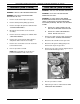
SERVICE MANUAL HALF-SIZE CONVECTION OVENS ELECTRIC AND GAS MODEL ML ELECTRIC ECO2D 114570 ECO2C 114572 GAS GCO2D 114569 GCO2C 114571 GCO2D Shown - NOTICE This Manual is prepared for the use of trained Vulcan Service Technicians and should not be used by those not properly qualified. If you have attended a Vulcan Service School for this product, you may be qualified to perform all the procedures described in this manual. This manual is not intended to be all encompassing.
HALF-SIZE CONVECTION OVENS TABLE OF CONTENTS GENERAL . . . . . . . . . . . . . . . . . . . . . . . . . . . . . . . . . . . . . . . . . . . . . . . . . . . . . . . . . . . . . . . . . . . . . . . . . . . . . Introduction . . . . . . . . . . . . . . . . . . . . . . . . . . . . . . . . . . . . . . . . . . . . . . . . . . . . . . . . . . . . . . . . . . . . . . . Specifications . . . . . . . . . . . . . . . . . . . . . . . . . . . . . . . . . . . . . . . . . . . . . . . . . . . . . . . . . . . . . . . . . . .
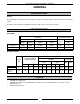
HALF-SIZE CONVECTION OVENS - GENERAL GENERAL INTRODUCTION General This manual will cover half-size electric and gas convection ovens that use either a solid state control or an electronic control. Procedures in this manual are applicable to both gas and electric ovens unless specified. SPECIFICATIONS GAS OVENS GAS DATA INPUT BTU/HR ELECTRICAL DATA MANIFOLD PRESSURE LOAD (Watts) AMP/LINE Natural Propane Natural Propane 120V Single Oven 2500 2500 3.5" W.C. 10"W.C.
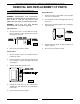
HALF-SIZE CONVECTION OVENS - REMOVAL AND REPLACEMENT OF PARTS REMOVAL AND REPLACEMENT OF PARTS COVERS AND PANELS Right Side Panel WARNING: DISCONNECT THE ELECTRICAL POWER TO THE MACHINE AT THE MAIN CIRCUIT BOX. PLACE A TAG ON THE CIRCUIT BOX INDICATING THE CIRCUIT IS BEING SERVICED. WARNING: SHUT OFF THE GAS BEFORE SERVICING THE UNIT. (When applicable) 1. Remove the three screws which secure the right side of the control panel. 2. Loosen the two screws on the right side of the top front cover. 3.
HALF-SIZE CONVECTION OVENS - REMOVAL AND REPLACEMENT OF PARTS CONTROL PANEL COMPONENTS Removable Components Listed on the illustration. Procedure WARNING: UNPLUG UNIT BEFORE SERVICING. 1. Remove the control panel as outlined under "COVERS AND PANELS". 5 2. Disconnect the wire leads at the component to be replaced. 3. Remove the component. 4. Reverse the procedure to install the new component, then check oven for proper operation.
HALF-SIZE CONVECTION OVENS - REMOVAL AND REPLACEMENT OF PARTS BLOWER AND/OR BLOWER MOTOR 8. A. B. C. D. WARNING: UNPLUG UNIT BEFORE SERVICING. 1. Remove racks and the right rack support. 2. Remove baffle panel by lifting up and out. 3. For gas ovens only, remove the heat exchanger as outlined under “HEAT EXCHANGER”. 4. Loosen set screws on blower hub. Disconnect the wire leads to the motor. 9.
HALF-SIZE CONVECTION OVENS - REMOVAL AND REPLACEMENT OF PARTS OVEN DOOR Disassembly Removal 1. Open the door. WARNING: UNPLUG UNIT BEFORE SERVICING. 2. Remove the door handle and latch plate. 1. Remove the top front cover as outlined under "COVERS AND PANELS". 3. Remove the screws which secure the inner and outer door panels to the door frame. 2. Remove the door switch lever from the door shaft. 3. Remove the door switch bracket. 4.
HALF-SIZE CONVECTION OVENS - REMOVAL AND REPLACEMENT OF PARTS DOOR SWITCH HEAT EXCHANGER (GAS OVENS) WARNING: UNPLUG UNIT BEFORE SERVICING. 1. Remove the top front cover as outlined under "COVERS AND PANELS". WARNING: UNPLUG UNIT BEFORE SERVICING. 2. Disconnect the leads to the door switch. WARNING: SHUT OFF THE GAS BEFORE SERVICING THE UNIT. 3. Remove the switch which is secured by two screws. 1. Remove racks and the right rack support. 2. Remove baffle panel by lifting up and out. 3.
HALF-SIZE CONVECTION OVENS - REMOVAL AND REPLACEMENT OF PARTS BURNER (GAS OVENS) GAS VALVE (GAS OVENS) WARNING: UNPLUG UNIT BEFORE SERVICING. WARNING: UNPLUG UNIT BEFORE SERVICING. WARNING: SHUT OFF THE GAS BEFORE SERVICING THE UNIT. WARNING: SHUT OFF THE GAS BEFORE SERVICING THE UNIT. WARNING: ALL GAS JOINTS DISTURBED DURING SERVICING MUST BE CHECKED FOR LEAKS. CHECK WITH A SOAP AND WATER SOLUTION (BUBBLES). DO NOT USE AN OPEN FLAME. 1. Remove racks and the right rack support. 2.
HALF-SIZE CONVECTION OVENS - REMOVAL AND REPLACEMENT OF PARTS HEATING ELEMENTS (ELECTRIC OVENS) TEMPERATURE PROBE Procedure WARNING: DISCONNECT THE ELECTRICAL POWER TO THE MACHINE AT THE MAIN CIRCUIT BOX. PLACE A TAG ON THE CIRCUIT BOX INDICATING THE CIRCUIT IS BEING SERVICED. 1. Remove racks and the right rack support. 2. Remove baffle panel by lifting up and out. 3. Remove the right side panel as outlined under “COVERS AND PANELS”. 4. Disconnect the lead wires to the heating elements. 5.
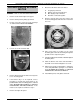
HALF-SIZE GAS CONVECTION OVENS - SERVICE PROCEDURES AND ADJUSTMENTS SERVICE PROCEDURES AND ADJUSTMENTS WARNING: CERTAIN PROCEDURES IN THIS SECTION REQUIRE ELECTRICAL TEST OR MEASUREMENTS WHILE POWER IS APPLIED TO THE MACHINE. EXERCISE EXTREME CAUTION AT ALL TIMES. IF TEST POINTS ARE NOT EASILY ACCESSIBLE, DISCONNECT POWER, ATTACH TEST EQUIPMENT AND REAPPLY POWER TO TEST. TEMPERATURE PROBE TEST (ALL MODELS) VERIFICATION OF SPARK AT SPARK PROBE WARNING: UNPLUG UNIT BEFORE SERVICING.
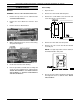
HALF-SIZE GAS CONVECTION OVENS - SERVICE PROCEDURES AND ADJUSTMENTS GAS PRESSURE ADJUSTMENT WARNING: UNPLUG UNIT BEFORE SERVICING. WARNING: SHUT OFF THE GAS BEFORE SERVICING THE UNIT. 1. Remove the right side panel and control panel as outlined under “COVERS AND PANELS”. 2. Remove the plug from the test port and install the manometer. GAS TYPE SETTING AT OUTPUT OF GAS VALVE Natural 3.5 inches W.C. Propane 10 inches W.C. NOTE: If input pressure is below 4.0 (Natural) or 10.5 (Propane) inches W.C.
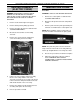
HALF-SIZE GAS CONVECTION OVENS - SERVICE PROCEDURES AND ADJUSTMENTS ELECTRONIC CONTROL SPECIAL KEY FUNCTIONS - To activate these functions press the specified keys while turning the oven on. You can not toggle between functions. Each function has to be entered from the off position. NOTE: There are four hidden keys on the control. See diagram following the table. HOLD KEYS 1&3 FUNCTION Calibration Mode 4&9 Change between (C & (F 6&8 Display test CALIBRATE OVEN - Perform Calibration at 350(F 1.
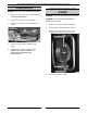
HALF-SIZE GAS CONVECTION OVENS - SERVICE PROCEDURES AND ADJUSTMENTS SOLID STATE CONTROL CALIBRATION SOLID STATE CONTROL TEST NOTE: Oven temperature must be below 450(F. 1. Place a thermocouple in the geometric center of the oven cavity. 1. Remove the screws from the control panel and pull the control panel away from the oven to access the control wiring. 2. Set the On-Off-Cool Down switch to ON. 3. Set the temperature control to 350 degrees F. 2.
HALF-SIZE GAS CONVECTION OVENS - SERVICE PROCEDURES AND ADJUSTMENTS 8. If the average temperature differs more than 10 degrees F from the dial settings: A. Pencil mark the knob pointer position as a reference point on the control panel next to the dial plate. B. Remove the temperature control knob. C. DOOR SWITCH ADJUSTMENT WARNING: DISCONNECT THE ELECTRICAL POWER TO THE MACHINE AT THE MAIN CIRCUIT BOX. PLACE A TAG ON THE CIRCUIT BOX INDICATING THE CIRCUIT IS BEING SERVICED. 1.
HALF-SIZE GAS CONVECTION OVENS - SERVICE PROCEDURES AND ADJUSTMENTS DOOR REVERSAL 7. WARNING: DISCONNECT THE ELECTRICAL POWER TO THE MACHINE AT THE MAIN CIRCUIT BOX. PLACE A TAG ON THE CIRCUIT BOX INDICATING THE CIRCUIT IS BEING SERVICED. 1. Remove the door switch from the switch mounting bracket. A. Use the other set of holes in the mounting bracket to mount the switch. B. Place the switch insulation pad on the mounting bracket. C. Install the switch onto the mounting bracket.
HALF-SIZE GAS CONVECTION OVENS - SERVICE PROCEDURES AND ADJUSTMENTS DOOR ADJUSTMENT BLOWER ADJUSTMENT WARNING: UNPLUG UNIT BEFORE SERVICING. 1. 2. WARNING: DISCONNECT THE ELECTRICAL POWER TO THE MACHINE AT THE MAIN CIRCUIT BOX. PLACE A TAG ON THE CIRCUIT BOX INDICATING THE CIRCUIT IS BEING SERVICED. The door should be parallel with the face of the oven cavity. If adjustment is needed: A. B. Remove the top front cover as outlined under “COVERS AND PANELS” in “REMOVAL AND REPLACEMENT OF PARTS”.
HALF-SIZE CONVECTION OVENS - ELECTRICAL OPERATION ELECTRICAL OPERATION COMPONENT FUNCTION POWER SWITCH . . . . . . . . . . . . . Controls power to oven. COOLDOWN SWITCH . . . . . . . . . Prevents heaters from operating and allows fan to run. (On some solid state control models, this switch is combined with the power switch) FAN SPEED SWITCH . . . . . . . . . . Controls speed of oven cavity blower motor. (Electric ovens) SOLID STATE CONTROL . . . . . . . Controls oven temperature. TIMER . . . . . . . . . .
HALF-SIZE CONVECTION OVENS - ELECTRICAL OPERATION COMPONENT LOCATION 19
HALF-SIZE CONVECTION OVENS - ELECTRICAL OPERATION Gas Oven SEQUENCE OF OPERATION NOTE: A combination of terminal numbers and wire numbers will be used to describe the circuit paths. The complete path will be described when a component is energized. Ignition Module 1. 24VAC supplied to ignition module as described under oven sequence of operation Solid State Control (Gas) A. 15 second prepurge period NOTE: Use GCO2D Schematic 1) 2) B. 1. Conditions A.
HALF-SIZE CONVECTION OVENS - ELECTRICAL OPERATION 6. Temperature is satisfied and control contacts 6/7 open A. Heat light goes out. B. Power removed from ignition transformer. 7. Ignition module de-energized A. Gas valve de-energized, gas supply to burner off. 8. Oven cycles on solid state control until power switch is moved from the "on" position or the door is opened.
HALF-SIZE CONVECTION OVENS - ELECTRICAL OPERATION 5. After verification of heat mode and door closed: Cook and Hold A. Ignition transformer primary powered: wire #26/43; J2-13; J2-15; J1-5; wire #5; BK/BL wire; WH/BK wire; wire #7; J1-7; wire #2; J12; Wire #2; L2 1) 24 VAC from secondary of ignition transformer to ignition module: wire #52; centrifugal switch; wire #54; terminal 24V of control module; GND 1.
HALF-SIZE CONVECTION OVENS - ELECTRICAL OPERATION 5. After verification of cooldown mode: A. B. C. Solid state relay energized: 16 to 18 VDC output on J2-11; J1-20; wire #20; wire #19; J1-19; J2-10 1) Blower motor energized: wire #26/4; J14; wire #4/34; ss relay contacts;; wire # 9; J1-9; wire #11; J1-11; wire #11; wire #13/7; J1-7; wire #2; J1-2; wire #2; L2 B.
HALF-SIZE CONVECTION OVENS - ELECTRICAL OPERATION 4. Buzzer sounds: wire #34/64; timer contacts 1/4; wire #66; wire #65/37 5. Timer turned to off. A. C. D. E. F. Contacts 1/4 open 1) buzzer de-energized 2. Power/cooldown switch turned "on" A. Cooldown (Elec/Solid State Control) NOTE: Use ECO2D Schematic 1. 2. Conditions A. A. Cooking completed, oven temperature needs to be lowered. B. Power switch on 4. Cooldown switch on A.
HALF-SIZE CONVECTION OVENS - ELECTRICAL OPERATION Cook Cooldown (Elec/Electronic Control) 1. NOTE: Use ECO2C Schematic 2. 3. Conditions A. Oven has reached set temperature in heat mode Time is set and start key pressed. Oven cycles at set temperature. NOTE: In pulse mode (initiated at the beginning of the bake cycle), the blower motor is operated in 45 second cycles, with the first cycle being off then 45 seconds on. The pulse time cannot be longer than the bake time. 1. Conditions A. B. 2.
HALF-SIZE CONVECTION OVENS - ELECTRICAL OPERATION SCHEMATICS GAS OVENS GCO2D 26
HALF-SIZE CONVECTION OVENS - ELECTRICAL OPERATION GCO2C 27
HALF-SIZE CONVECTION OVENS - ELECTRICAL OPERATION WIRING DIAGRAM - GAS OVENS GCO2D - Control Section 28
HALF-SIZE CONVECTION OVENS - ELECTRICAL OPERATION GCO2D - Oven Section 29
HALF-SIZE CONVECTION OVENS - ELECTRICAL OPERATION GCO2C - Control Section 30
HALF-SIZE CONVECTION OVENS - ELECTRICAL OPERATION GCO2C - Oven Section 31
HALF-SIZE CONVECTION OVENS - ELECTRICAL OPERATION SCHEMATIC-ELECTRIC OVENS ECO2D 32
HALF-SIZE CONVECTION OVENS - ELECTRICAL OPERATION ECO2C 33
HALF-SIZE CONVECTION OVENS - ELECTRICAL OPERATION WIRING DIAGRAM ELECTRIC OVENS ECO2D - Control Section 34
HALF-SIZE CONVECTION OVENS - ELECTRICAL OPERATION ECO2D - Oven Section 35
HALF-SIZE CONVECTION OVENS - ELECTRICAL OPERATION ECO2C - Control Section 36
HALF-SIZE CONVECTION OVENS - ELECTRICAL OPERATION ECO2C - Oven Section 37
HALF-SIZE CONVECTION OVENS - ELECTRICAL OPERATION TROUBLESHOOTING ELECTRIC OVENS SYMPTOM POSSIBLE CAUSES No power to oven controls. 1. 2. 3. Main breaker open. Control circuit fuses open. 12/6 volt transformer inoperative. (Electronic control) No oven operation; power to controls. 1. 2. Door switch open. Temp. control malfunction. Blower motor operates when oven is heating, but not in cooldown. 1. Cooldown switch inoperative (solid state control). Blower motor does not operate, oven heats. 1.
HALF-SIZE CONVECTION OVENS - TROUBLESHOOTING GAS OVENS SYMPTOM POSSIBLE CAUSES No power to oven controls. 1. 2. 3. Unit unplugged Power switch inoperative. 12/6 volt transformer inoperative. (Electronic control) No oven operation; power to controls. 1. 2. Door switch open or inoperative. Solid state relay malfunction. (Electronic control) Blower motor malfunction. Electronic control malfunction. 3. 4. Gas does not ignite; no spark. 1. 2. 3. 4. 5. 24 volt transformer not functioning.
Form 24575 (12/96) Printed in U.S.A.