SERVICE MANUAL C24EA SERIES ELECTRIC CONVECTION STEAMERS C24EA6 C24EA10 ML-136058 ML-136059 C24EA6 SHOWN - NOTICE This Manual is prepared for the use of trained Vulcan Service Technicians and should not be used by those not properly qualified. If you have attended a Vulcan Service School for this product, you may be qualified to perform all the procedures described in this manual. This manual is not intended to be all encompassing.
MODEL C24EA TABLE OF CONTENTS GENERAL . . . . . . . . . . . . . . . . . . . . . . . . . . . . . . . . . . . . . . . . . . . . . . . . . . . . . . . . . . . . . . . . . . . . . . . . . . . . . . . . 3 COVERS AND PANELS . . . . . . . . . . . . . . . . . . . . . . . . . . . . . . . . . . . . . . . . . . . . . . . . . . . . . . . . . . . . . . . . . . . . . 5 DOOR . . . . . . . . . . . . . . . . . . . . . . . . . . . . . . . . . . . . . . . . . . . . . . . . . . . . . . . . . . . . . . . . . . . . . . . . . .
MODEL C24EA - GENERAL GENERAL INTRODUCTION This manual is applicable to the models and ML numbers listed on the cover page. Procedures apply to all models unless specified otherwise. Steam Cooking Convection steamers offer an efficient way to produce many foods in either small portions or larger batches. Convection steam cooking will steam cook fresh foods or will steam defrost and cook frozen foods providing the maximum color, flavor and nutritional value with the least expenditure of energy and labor.
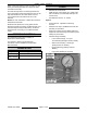
MODEL C24EA - GENERAL Other chemical properties in water supplies can also affect good steam generation and vary from within each state and locality. TOOLS • Standard set of hand tools. The water level probes in the steam generator use ions in the water to detect the water level. Do not use fully demineralized or de-ionized water since it is non-conductive and the water level can not be detected.
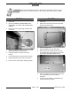
MODEL C24EA - COVERS AND PANELS COVERS AND PANELS FRONT BASE PANEL 1. RIGHT AND LEFT SIDE BASE PANELS Remove screws from the bottom of panel. NOTE: Removal of left side panel is identical to the procedure for the right side panel. 2. Pull bottom of panel out and slide down to clear tabletop cover. 3. Reverse procedure to install. 1. Remove FRONT BASE PANEL. 2. Remove screws from the bottom of panel. 3. Pull bottom of panel out and slide down to clear tabletop cover. 4.
MODEL C24EA - COVERS AND PANELS REAR BASE PANEL COOKING COMPARTMENT RIGHT AND LEFT SIDE PANELS 1. Remove electrical power connection to machine. 2. Turn off water supply and disconnect plumbing to machine. 3. Remove screws securing water valves to panel. 4. Remove screws from the bottom of panel. 5. Pull bottom of panel out and slide down to clear tabletop cover. 6. Reverse procedure to install.
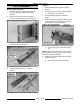
MODEL C24EA - DOOR DOOR REMOVAL GASKET 1. Close door. 1. Open door. 2. Remove COOKING COMPARTMENT LEFT SIDE PANEL as outlined under COVERS AND PANELS. 2. Remove the shoulder screws and pan pusher bracket from gasket plate. 3. Remove nuts from upper hinge located inside front panel. 3. Remove gasket plate. 4. Remove gasket from inner door panel. 5. Remove RTV from bottom part of inner door panel. Apply RTV 109 to bottom of door where shown when assembling gasket to door. 6.
MODEL C24EA - DOOR DOOR HANDLE Removal 1. Open door. 2. Remove screws from top and bottom of door assembly. 3. 4. Install lock nuts and tighten until no gap exists between handle, step spacer and lock nut. Do not over-tighten lock nuts. 5. Close inner door panel so that latch mechanism engages striker on front panel. 6. Install outer door housing onto inner door panel. 7. Align the top and bottom screw holes of outer door housing with inner door panel. 8.
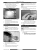
MODEL C24EA - DOOR Assembly LATCH ASSEMBLY 1. Apply Lubriplate 630AA to sides of sliding bracket. Separate outer door housing assembly from inner door panel as outlined under DOOR HANDLE. 2. Insert spring pin into bottom of sliding bracket. Remove screws securing latch assembly to inner door panel and remove latch mechanism. 3. Assemble sliding bracket into stationary bracket. 4.
MODEL C24EA - DOOR Installation 8. 1. Do not drive bearing into place. The inner door panel could be damaged. Press bearing into position. Install latch assembly onto inner door panel with spring pin toward bottom of door panel. A. Apply Loctite 271 to threads of screws before assembly and secure latch assembly to inner door panel. NOTE: When replacing door hinge bearings, replace both hinge bearings. 9. 2. Install outer door housing assembly as outlined under DOOR HANDLE. 3.
MODEL C24EA - DOOR B. C. Locate the striker that catches on door latch near steam chamber on front panel. Adjustment 1. Reinstall striker with slot pointing upward and hand tighten nut only. 2. Close door to center striker in front panel mounting hole. 3. Open door and check striker slot for horizontal alignment. The slot on striker must be kept horizontal in order for door latch to catch properly and latch. 4.
MODEL C24EA - THERMOSTATS AND HIGH LIMITS THERMOSTAT AND HIGH LIMITS HEAT EXCHANGER HIGH LIMIT STEAM GENERATOR HIGH LIMIT Removal 1. Turn off machine to drain steam generator. Allow steamer to complete drain cycle. 2. Remove RIGHT SIDE BASE PANEL as outlined under COVERS AND PANELS. 3. Disconnect electrical lead wires from heat exchanger high limit. 2. Remove FRONT BASE PANEL as outlined under COVERS AND PANELS. 4.
MODEL C24EA - THERMOSTATS AND HIGH LIMITS 4. Secure high limit to low voltage control box then coil excess capillary tube length near the high limit. 5. Check steamer for proper operation and leaks around heating element gasket and high limit capillary tube nuts. CONDENSATE THERMOSTAT 1. RIGHT SIDE SHOWN 8. A. Remove capillary tube from heating element. Installation 1. Route capillary bulb through the opening in heating element mounting plate.
MODEL C24EA - TIMERS TIMERS REMOVAL AND REPLACEMENT NOTE: When the timer reaches zero, an external buzzer will sound and steam will stop entering the cooking compartment. The constant steam setting allows for continuous steam operation. 1. Remove COOKING COMPARTMENT RIGHT SIDE PANEL as outlined under COVERS AND PANELS. 2. Note electrical connections then disconnect wiring from timer being serviced. 4. Reverse procedure to install. 5. Check steamer for proper operation. UPPER COMPARTMENT SHOWN 3.
MODEL C24EA - HEATING ELEMENTS AND CONTACTORS HEATING ELEMENTS AND CONTACTORS REMOVAL AND REPLACEMENT Heating Elements 1. Turn off machine to drain steam generator. Allow steamer to complete drain cycle. A. Turn off water supply. 2. Remove FRONT BASE PANEL as outlined under COVERS AND PANELS. 3. Remove top screw securing cover to high voltage box. 4. Note electrical connections for the heating element being replaced then disconnect heating element lead wires from contactors.
MODEL C24EA - HEATING ELEMENTS AND CONTACTORS Contactors HEATING ELEMENTS DIAGNOSTIC CHECK 1. Turn off machine to drain steam generator. Allow steamer to complete drain cycle. 2. Remove FRONT BASE PANEL as outlined under COVERS AND PANELS. 3. Remove top screw securing cover to high voltage box. 4. Note electrical connections for the contactor being replaced then disconnect lead wires from contactor terminals and coil. 5.
MODEL C24EA - HEATING ELEMENTS AND CONTACTORS 3. 4. If unable to check current draw, a resistance check may indicate a malfunctioning element. A. Turn power switch off and disconnect power to machine. B. Disconnect heating element lead wires and check the individual element resistance using a VOM. C. If resistance readings are not correct, replace heating element. Check steamer for proper operation. VOLTAGE KW PER CURRENT PER ELEMENT ELEMENT RESISTANCE PER ELEMENT (OHMS) 208 1 1 2 8.0 12.
MODEL C24EA - HEAT EXCHANGER ELEMENTS AND RELAYS HEAT EXCHANGER ELEMENTS AND RELAYS REMOVAL AND REPLACEMENT Heat Exchanger Elements 1. Turn off machine to drain steam generator. Allow steamer to complete drain cycle. A. Turn off water supply. 2. Remove FRONT BASE PANEL and RIGHT SIDE BASE PANEL as outlined under COVERS AND PANELS. 3. Note electrical connections for the heat exchanger element being replaced then disconnect lead wires from heat exchanger relay and contactor.
MODEL C24EA - HEAT EXCHANGER ELEMENTS AND RELAYS HEAT EXCHANGER ELEMENTS DIAGNOSTIC CHECK 1. 6. Reassemble parts removed in reverse order. Apply pipe thread sealant to threads of heat exchanger element before assembly. 7. Check steamer for proper operation and leaks around heat exchanger element. Check voltage across heat exchanger element lead wires at the limiting and regulating contactor terminals and verify against data plate. A. If voltage is correct, check current draw (step 2). B.
MODEL C24EA - HEAT EXCHANGER ELEMENTS AND RELAYS 3. 4. If unable to check current draw, a resistance check may indicate a malfunctioning element. A. Turn power switch off and disconnect power to machine. B. Disconnect heat exchanger element lead wires and check resistance using a VOM. C. If resistance is not correct, replace heat exchanger element. Check steamer for proper operation.
MODEL C24EA - WATER LEVEL CONTROL COMPONENTS WATER LEVEL CONTROL COMPONENTS WATER LEVEL CONTROL - LOW LEVEL CUT-OFF AND DIFFERENTIAL OPERATION The steamer is equipped with three water level sensing probes (high, low and low level cut-off) and a water level control. The water level control performs two functions: 1. Provide low level cut-off protection to shut off the heat source in case the water level drops below the low level cut-off (LLCO) probe. 2.
MODEL C24EA - WATER LEVEL CONTROL COMPONENTS WATER LEVEL CONTROL WATER LEVEL PROBES 1. Remove FRONT BASE PANEL as outlined under COVERS AND PANELS. 2. Squeeze tab on plastic standoffs (5) to release water level control. 1. Remove RIGHT SIDE BASE PANEL as outlined under COVERS AND PANELS. 2. Note locations of electrical wiring and disconnect lead wires to water level probes.
MODEL C24EA - WATER LEVEL CONTROL COMPONENTS FILTERED AND NON-FILTERED DUAL WATER SOLENOID VALVES NOTE: The filtered and non-filtered water solenoid valves are constructed as dual water valve assemblies. The two water valve assemblies used on the steamer have different flow rates and should not be interchanged. DUAL WATER VALVE FLOW RATES (GPM) 1. Filtered Water Fast Fill/Flush Valve Slow Fill Valve (Steam Generator Fill) (3SOL) (4SOL) 4.8 0.
MODEL C24EA - WATER LEVEL CONTROL COMPONENTS 6. Remove screws (2) securing dual water solenoid valve to rear panel. 7. Reassemble parts removed in reverse order. 8. Verify water supply is connected to the correct dual water solenoid valve (filtered or non filtered). 9. Check steamer for leaks and proper operation. 5. MOTORIZED DRAIN VALVE 1. Push in on the manual drain override knob to disengage the gear set. A. Rotate knob CW to manually open the drain valve.
MODEL C24EA - WATER LEVEL CONTROL COMPONENTS 8. Reassemble parts removed in reverse order. Apply pipe thread sealant to pipe threads before installation. NOTE: If motorized drain valve is in the open position when power is applied to the steamer with the power switch on, drain valve will not close and fill water will flow through the steam generator into the drain. 9. Verify power switch is in the off position and the motorized drain valve is closed before applying power to steamer.
MODEL C24EA - SWITCHES, SOLENOIDS, RELAY, AND BUZZER SWITCHES, SOLENOIDS, RELAYS AND BUZZER POWER AND DELIME SWITCHES NOTE: If replacing the switch assembly (gaskets, power and delime switches), remove the switch bezel from the front panel. 5. Reassemble parts removed in reverse order. 6. Check steamer for proper operation. DOOR SWITCH 1. Remove COOKING COMPARTMENT RIGHT SIDE PANEL as outlined under COVERS AND PANELS. 2. Locate switch on front panel. Removal 1.
MODEL C24EA - SWITCHES, SOLENOIDS, RELAY, AND BUZZER Installation 1. 2. 3. Verify E-clip is installed on door switch linkage in groove nearest front panel. Remove FRONT BASE PANEL as outlined under COVERS AND PANELS. 3. Locate pressure switch on the left side of the switch piping assembly. 4. Disconnect electrical wiring to pressure switch. 5. Remove pressure switch from piping. 6. Reassemble parts removed in reverse order. Loosely install door switch onto door switch mounting bracket. A.
MODEL C24EA - SWITCHES, SOLENOIDS, RELAY, AND BUZZER NOTE: Operating pressures will vary slightly between machine being serviced and gauge used. Check NOTE: Pressure can be checked with the small air pocket that exists between the delime port cap and water level probe housing in the delime hose. Make certain that no leaks exist in the steam generator connections or pressure gauge fittings. 1. Turn off machine to drain steam generator. Allow steamer to complete drain cycle. 2.
MODEL C24EA - SWITCHES, SOLENOIDS, RELAY, AND BUZZER B. Check cut-out pressure after making adjustment. Repeat Check and Adjustment as necessary until cut-out pressure is within 3.5 to 3.7 psi. VACUUM RELIEF SOLENOID PRESSURE SWITCH (2PAS) 1. Turn off machine to drain steam generator. Allow steamer to complete drain cycle. 2. Remove FRONT BASE PANEL as outlined under COVERS AND PANELS. 3. Locate pressure switch on the right side of the switch piping assembly. 1.
MODEL C24EA - SWITCHES, SOLENOIDS, RELAY, AND BUZZER COMPARTMENT STEAM SOLENOID 1. 2. 3. TIME DELAY RELAY 1. Turn off machine to drain steam generator. Allow steamer to complete drain cycle. Turn off machine to drain steam generator. Allow steamer to complete drain cycle. 2. Remove RIGHT SIDE BASE PANEL as outlined under COVERS AND PANELS. Remove FRONT BASE PANEL as outlined under COVERS AND PANELS. 3. Locate compartment steam solenoid connected to cooking compartment.
MODEL C24EA - SWITCHES, SOLENOIDS, RELAY, AND BUZZER BUZZER 1. Remove COOKING COMPARTMENT RIGHT SIDE PANEL as outlined under COVERS AND PANELS. 2. Locate buzzer on the door switch mounting bracket. 3. Disconnect electrical wiring from the buzzer and door switch. 4. Remove door striker. 5. Remove remaining hardware securing door switch mounting bracket to front panel then remove door switch mounting bracket, door switch and buzzer as an assembly. 6.
MODEL C24EA - CONTROL BOARD CONTROL BOARD REMOVAL AND REPLACEMENT 1. Remove FRONT BASE PANEL as outlined under COVERS AND PANELS. 2. Disconnect electrical connectors from control board. 3. Squeeze tab on plastic standoffs (10) to release control board. 4. Reassemble parts removed in reverse order. 5. Check steamer for proper operation.
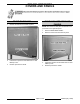
MODEL C24EA - CONTROL BOARD LAYOUT AND LED LEGEND The control board provides a central location for wire harness connections and power transfer through board relays (K1-K9, and K11) and time delay relays (delime 1, delime 2 and drain) to the steamer controls. Also, provides a condition or component troubleshooting indicator by utilizing eighteen LED’S on the board. LED LEGEND LED ON = Condition satisfied or component energized. LED OFF = Condition not satisfied or component de-energized.
MODEL C24EA - CONTROL BOARD STEAM GENERATOR OPERATIONAL STATUS (LED INDICATORS) Use the tables below to determine the operational status of a component or condition by utilizing the LED indicators on the board. The sections are divided according to their operational step. NOTE: If steamer power switch is off when line voltage applied, the steamer enters a timed drain cycle then shuts off. Starting Conditions • Power and water supplied to steamer. • Power switch (1S) off.
MODEL C24EA - CONTROL BOARD Water Level at LLCO Probe • LLCO LED is on (water level control) (LED is on until water drops below LLCO probe). • All contactors energized (steam generator begins heating). • Water fill of the steam generator changes to slow fill rate. LED STATUS ON 1 X 2 X 3 X 4 X 12 X COMPONENT OFF DESCRIPTION Same as Starting Conditions Limiting contactor (1CON) energized. Water level is satisfied (LLCO probe).
MODEL C24EA - CONTROL BOARD Steam Generator at Operating Pressure • Ready lights (1LT) (green) lit for the upper and lower compartments. • All contactors de-energized (heating stops). LED STATUS ON 1 X 2 X 3 5 DESCRIPTION Same as Starting Conditions X 4 COMPONENT OFF X X Same as Water Level at LLCO Probe Limiting contactor (1CON) remains energized with the water level satisfied (LLCO probe). Regulating contactor 1 (2CON) deenergized. Power removed from heating elements.
MODEL C24EA - CONTROL BOARD Timers Reach Zero (Upper and lower Compartments) • Buzzer sounds until timer turned to off, constant or additional time is set. • Cook lights (2LT) (red) turn off and cooking compartment steam solenoids de-energize. • Heat exchanger heating elements de-energize. • LED 3 and 4 will cycle as described under Timers Set (Upper and lower Compartments). LED STATUS ON COMPONENT OFF 1 X Same as Starting Conditions 2 X Same as Water Level at LLCO Probe.
MODEL C24EA - CONTROL BOARD DELIMING CYCLE STATUS (LED INDICATORS) • • Conditions same as listed under STARTING CONDITIONS. Delime time delay relay 2 (TDR) and drain time delay relay (TDR) jumpers on the control board are set at their default times as shown on the schematic. • Delime valve closed. • Delime solution added to steam generator. NOTE: Heat exchanger elements are not energized during delime cycle. Delime Switch On • Delime switch pressed to DELIME position (momentary on - hold 2 sec).
MODEL C24EA - CONTROL BOARD Water Level at LLCO Probe • LLCO LED is on (water level control) (LED is on until water drops below LLCO probe). • All contactors energized (steam generator begins heating). • Water fill of the steam generator changes to slow fill rate.
MODEL C24EA - CONTROL BOARD Steam Generator at Operating Pressure • All contactors de-energized (heating stops). LED STATUS ON 1 X 2 X COMPONENT OFF DESCRIPTION Same as Starting Conditions 3 X 4 X Same as Water Level at LLCO Probe Limiting contactor (1CON) remains energized with the water level satisfied (LLCO probe). Regulating contactor 1 (2CON) deenergized. Power removed from heating elements. Regulating contactor 2 (3CON) deenergized. Power removed from heating elements.
MODEL C24EA - CONTROL BOARD LED 1 STATUS ON COMPONENT OFF X DESCRIPTION Same as Starting Conditions 3 X Regulating contactor 1 (2CON) deenergized. Power removed from heating elements. 5 X Relay (K1) de-energized. Pressure switch (1PAS) contacts close. Drain (TDR) energized thru K4-6/2 contacts. 120VAC output from drain (TDR) load terminal. Drain circuit energized. Drain relay (K5) is energized thru delime valve end switch closed contacts (N.O.).
MODEL C24EA - HEAT EXCHANGER HEAT EXCHANGER REMOVAL AND REPLACEMENT 1. Turn off machine to drain steam generator. Allow steamer to complete drain cycle. A. Turn off water supply. 2. Remove FRONT and RIGHT SIDE BASE PANELS as outlined under COVERS AND PANELS. 3. Disconnect heat exchanger element wiring as outlined under HEAT EXCHANGER ELEMENTS AND RELAYS. 4. Remove control assembly from MOTORIZED DELIME VALVE. 5. Disconnect lead wires from HEAT EXCHANGER HIGH LIMIT. 6.
MODEL C24EA - HEAT EXCHANGER MOTORIZED DELIME VALVE NOTE: The motorized delime valve (normally closed) can be opened or closed manually by pushing in on the manual override knob on top of the valve to disengage the gear set. Rotate knob CW to open the valve (slot in knob vertical); or CCW to close the valve (slot in knob is horizontal). Removal 1. Turn off power to machine. Allow steamer to complete drain cycle. A. Turn off water supply to steamer. 2.
MODEL C24EA - STEAM GENERATOR STEAM GENERATOR REMOVAL AND REPLACEMENT 1. Turn off machine to drain steam generator. Allow steamer to complete drain cycle. A. Turn off water supply. 2. Remove FRONT, LEFT and RIGHT SIDE BASE PANELS from generator base and COOKING COMPARTMENT RIGHT SIDE PANEL as outlined under COVERS AND PANELS. 3. Remove HEAT EXCHANGER. 4. Remove VACUUM RELIEF SOLENOID. 5. Disconnect compressions fittings then remove condensate coil tubing. 6.
MODEL C24EA - STEAM GENERATOR C. Remove four bolts securing high voltage control box to frame. 16. 12. Remove low voltage control box from steamer. A. Remove the following parts from steam generator for reuse: A. Drip shield (above elements). B. Remaining pipe nipples, tees and elbows. 17. If removed or replacing steam generator, install insulation around the generator. Secure into position using high temperature aluminum foil tape. 18. Reinstall parts removed in reverse order.
MODEL C24EA - ELECTRICAL OPERATION ELECTRICAL OPERATION COMPONENT FUNCTION STEAM GENERATOR CONTROLS Water Level Control (WLC) . . . . . . . . . . . . . . . Controls water level by monitoring conditions of the three water level probes H, L and LLCO. Probe (H) . . . . . . . . . . . . . . . . . . . . . . . . . . . . . High water level probe connected to internal latch relay circuit on WLC. Water must reach this level before internal latch relay is energized. Probe (L) . . . . . . . . . . . . . . . . . . . .
MODEL C24EA - ELECTRICAL OPERATION Solenoid, Delime Valve . . . . . . . . . . . . . . . . . . Controlled by delime relay K7 and drain circuit operation. When energized by 24VAC, valve opens to allow deliming of the heat exchanger and elements during a delime cycle. Switch (1PAS), Pressure . . . . . . . . . . . . . . . . . Pressure cut-out protection. Range is between 4.5 to 4.7 psi. Removes power from heating circuit if steam generator pressure rises above the pressure switch setting.
MODEL C24EA - ELECTRICAL OPERATION Relay (K9), Cavity . . . . . . . . . . . . . . . . . . . . . . Controlled by lower cooking compartment timer. When timer is set, relay is energized and power is provided thru K8-1/5 N.C. contacts to cavity condensate solenoid and heat exchanger relay (K11). Heat exchanger element (2) energized. Relay (K11), High Limit . . . . . . . . . . . . . . . . . . Controlled by high limit thermostat (2TAS). Relay is energized if high limit thermostat opens.
MODEL C24EA - ELECTRICAL OPERATION COMPONENT LOCATION Steam Generator Base Page 49 of 68 F35453 (July 2008)
MODEL C24EA - ELECTRICAL OPERATION F35453 (July 2008) Page 50 of 68
MODEL C24EA - ELECTRICAL OPERATION Water Level Control Cooking Compartment Controls Page 51 of 68 F35453 (July 2008)
MODEL C24EA - ELECTRICAL OPERATION SMART CYCLE POWER MANAGEMENT Reduces energy use by not powering all the heating elements in steam generator and heat exchanger when the steamer is at operating pressure and one cooking compartment in use. When both cooking compartments are in use, all of the heating elements in the steam generator and heat exchanger are powered.
MODEL C24EA - ELECTRICAL OPERATION K. Pressure switch (1PAS) closed. L. Drain valve closed and steam generator is empty. M. Delime valve closed and heat exchanger empty. 1) N. 2. Water level control (WLC) and steam generator properly grounded. Power switch turned on (1S). A. LED 13 off. Power removed from delime 1 (TDR) on control board. B. LED 9 off. Power removed from drain (TDR) on control board. C. X1 potential thru steam generator high limit (2TAS) and heat exchanger high limit (3TAS).
MODEL C24EA - ELECTRICAL OPERATION a) b. K1-5/1 N.C. contacts open. a) 2) B. Ready lights (1LT) (green) are lit for the upper and lower compartments. LED 4 off. Regulating contactor 2 (3CON) de-energized. LED 3 off. Regulating contactor 1 (2CON) de-energized. Power removed from heating elements. Steam generator heating stops. Timers Set (Upper & Lower Compartments) 1. Timers set for timed cooking and doors closed. A. Upper compartment - Timer contacts 11/13 and 21/23 close. 1) B. LED 6 lit.
MODEL C24EA - ELECTRICAL OPERATION 2) HL LED off. High level (HL) coil de-energized by ILR-2 contacts opening. a. 2. WLC (HL) contacts open. Slow fill solenoid (4SOL) de-energized. Timers reach zero (Upper & Lower Compartments). A. Upper compartment - Timer contacts 11/13 and 21/23 open. 1) B. LED 6 off. Upper cavity relay (K8) de-energized. K8-3/5 contacts return to N.O. condition. a. LED 8 off. Cavity condensate solenoid (2SOL) de-energized. b. Heat exchanger relay (K10) de-energized.
MODEL C24EA - ELECTRICAL OPERATION 6. LED 13 Lit. Power to delime 1 (TDR). Time delay relay has no output from load terminal until input trigger voltage is received by delime switch (2S) at the start of a delime cycle. 7. Water level drops below low level (L) probe. 8. A. Internal latching relay coil (ILR) on WLC de-energized. ILR-1 contacts return to N.O. condition. B. HL LED lit. High level coil (HL) energized by ILR-2 contacts returning to N.C. condition. WLC (HL) contacts close.
MODEL C24EA - ELECTRICAL OPERATION a. Delime relay (K2) remains powered. LED 15 remains lit from pressing delime switch (2S). b. Power to heating circuit, power light (3LT) (amber) and WLC thru K4-5/3 closed contacts (N.O.). a) 3. Steam generator fills and operates as outlined in steps 2A thru 7B under Initial Fill and Pre-heat with this exception. After pressure switch (1PAS) is satisfied, LED 4 will remain off and regulating contactor 2 (3CON) will remain de-energized.
MODEL C24EA - ELECTRICAL OPERATION SCHEMATIC DIAGRAMS F35453 (July 2008) Page 58 of 68
MODEL C24EA - ELECTRICAL OPERATION - THIS PAGE INTENTIONALLY LEFT BLANK - Page 59 of 68 F35453 (July 2008)
MODEL C24EA - ELECTRICAL OPERATION Steam Generator Base F35453 (July 2008) Page 60 of 68
MODEL C24EA - ELECTRICAL OPERATION Page 61 of 68 F35453 (July 2008)
MODEL C24EA - ELECTRICAL OPERATION WIRING DIAGRAMS Heating Element Wiring F35453 (July 2008) Page 62 of 68
MODEL C24EA - ELECTRICAL OPERATION Page 63 of 68 F35453 (July 2008)
MODEL C24EA - ELECTRICAL OPERATION F35453 (July 2008) Page 64 of 68
MODEL C24EA - ELECTRICAL OPERATION Cooking Compartment Page 65 of 68 F35453 (July 2008)
MODEL C24EA - TROUBLESHOOTING TROUBLESHOOTING Before performing any of the troubleshooting checks listed below, remove the front generator base panel and check the LED’S on the control board for the status of the condition or component in the operating sequence. By utilizing the troubleshooting LED’S, the Service Technician can easily determine if a component is functioning properly or in need of repair. Refer to CONTROL BOARD. SYMPTOM Drain water not being cooled properly.
MODEL C24EA - TROUBLESHOOTING SYMPTOM Steamer will not heat. 1. 2. 3. 4. 5. 6. Steam generator not filling or is slow to fill. 7. 8. 9. 10. 11. 12. 13. 14. 1. 2. 3. 4. 5. 6. 7. 8. 9. Steam leaks around door. Water leaks around door. Steam generated inside cooking compartment when timer is off. Timer motor does not run Door not closing properly. Door won’t open. Buzzer not operating. 10. 11. 1. 2. 1. 2. 3. 1. 2. 1. 2. 1. 2. 1. 1. 2. POSSIBLE CAUSES Check incoming voltage. Steam generator not filled.
MODEL C24EA - TROUBLESHOOTING -NOTES- F35453 (July 2008) Printed in U.S.A.