
Hardware manual


5Hardware Layout
© 2008 Apollo Security Inc.
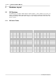
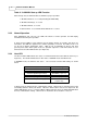
Baud Rate
2
3
300
OFF
OFF
1200
OFF
ON
2400
ON
OFF
9600
ON
ON
Note: Switch 8 is not used.
Table 2. 1:
ASA-72 DIP Switch Settings
2.1.2 DIP Switch Function
Communications Address
—Sets the address that identifies the device on the communications
line. This number must be unique for each device on a single RS-485 communications line.
Baud Rate
—Specifies the baud rate for the serial line of interface. This setting must be the
same for all devices on the communication line connected to this port.
Table 2.1.1 : DIP Switch Function
2.2 LEDs
The ASA-72 has 77 LEDs on the front panel for use in monitoring functioning of panel,
annunciating alarms and for diagnosis of problems. The LEDs function in two modes: startup and
normal operation
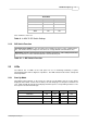
2.2.1 Start Up Mode
Immediately after powering on the panel, the start-up test will initiate and the results will be
displayed on the LEDs. If there are no failures, the test will progress If the panel encounters an
error, it will stop with the failed test and display the LED sequence corresponding to that test. The
first sequence tests the internal logic:
Test
A1
A2
A3
A4
Initilization
ON
OFF
OFF
OFF
Internal RAM
ON
ON
OFF
OFF
External RAM
ON
ON
ON
OFF
PROM CRC Check
ON
ON
ON
ON