
Hardware manual


ASA-72 Hardware ManualI
© 2008 Apollo Security Inc.
Table of Contents
Part I Introduction
2
................................................................................................................................... 21 Overview
................................................................................................................................... 22 General Features
Part II Hardware Layout
4
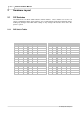
................................................................................................................................... 41 DIP Switches
......................................................................................................................................................... 4DIP Switch Tables
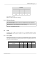
......................................................................................................................................................... 5DIP Switch Function
................................................................................................................................... 52 LEDs
......................................................................................................................................................... 5Start Up Mode
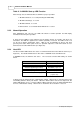
......................................................................................................................................................... 6Normal Operation
......................................................................................................................................................... 6Host LED
................................................................................................................................... 73 Firmware
................................................................................................................................... 74 Additional Installation Information
......................................................................................................................................................... 8Mounting
Part III System Wiring
10
................................................................................................................................... 101 Power
................................................................................................................................... 102 RS-485 Communication Line
................................................................................................................................... 103 General Alarm Inputs
......................................................................................................................................................... 10Cabinet Tamper
......................................................................................................................................................... 10Power Fault Input
......................................................................................................................................................... 10Keyswitch/ACK Switch Wiring (Optional)
Part IV Specifications
12
Part V Supplemental Figures
14
Part VI Table of Figures
24
Part VII Revision History
26
Index
27