
Hardware manual


6 ASA-72 Hardware Manual
© 2008 Apollo Security Inc.
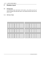
Table 2. 2:
AIM-2SL Start up LED Function
After the logic test, the LED test will test all LEDs for proper operation:
1. All LEDs ON Green, .5 second (Including ON LINE LEDs)
2. All LEDs ON Orange, .5 second
3. All LEDs ON Red, .5 second
4. Buzzer ON for .5 second and HOST LED ON for 1 second.
2.2.2 Normal Operation
After initialization and self tests, the LEDs will switch to normal operation and will display
information about the panel operation.
A single tri-color LED per zone indicates Red for Alarm, Orange for Trouble, and Green for
Non-alarm. The LEDs are organized as 4 columns (A,B,C,D,) of 19 each. The LEDs of rows 1-18
are tri-color to display alarm/reader status. LEDs of row 19 (ONLINE) are Green, and show
general panel status. Name plate inserts are provided adjacent to each LED column for user
defined text to describe LED function (See Figure 61).
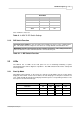
2.2.3 Host LED
The Green HOST LED indicates the status of communication between the ASA-72 and host (see
Figure 55). The HOST LED functions in two modes: NORMAL mode and TEST mode.
In NORMAL mode, the LED has four states. The four states and the LED activity are shown
below:
State
LED Activity
Communication Normal
Solid Green
Comm Lost (Request For
Acknowledgement generated)
Slow Blink (1 per sec)
Comm Lost (Being acknowledged)
Fast Blink (5 per sec)
Comm Lost (Acknowledged)
Heart beat
(1 per 5 sec)
In TEST mode, the LED shows the communication activity. TEST mode is entered by depressing
and holding down the TEST push button. When the TEST button is detected as depressed, the
HOST LED will turn on for 1 second to fulfill the LED test function, then, the HOST LED will follow
the host communication activity. TEST mode is exited when the test button is released.