F55b INSTRUCTION MANUAL We’ll Make It Stress-Free If you have any questions along the way, just give us a call. 1-888-333-9952. We’re ready to help! Scan for easy install video san.
IMPORTANT SAFETY INSTRUCTIONS – SAVE THESE INSTRUCTIONS – PLEASE READ ENTIRE MANUAL PRIOR TO USE Before You Begin Please check the following items: Your TV and any accessories you plan to use do not exceed the specified weight limit. The hole pattern on the back of your TV is compatible with the hole pattern of the TV brackets. The wall you chose to mount your TV is wood stud, solid concrete, or concrete block. You read and understand these directions.
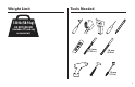
Weight Limit Tools Needed 130 lb (58.9 kg) DO NOT EXCEED! (includes TV and any accessories) 5.5 mm (7/32 in.) 10 mm (3/8 in.) 13 mm (1/2 in.
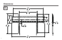
Dimensions in. [mm] 25.40 645.2 UP TO 26.57 675.0 3.91 99.4 6.54 166.2 17.24 437.9 15.94 405.0 3.36 85.2 OFFSET 28.12 714.3 4 0.95 24.
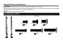
Supplied Parts and Hardware WARNING: This product contains small items that could be a choking hazard if swallowed. Before starting assembly, verify all parts are included and undamaged. If any parts are missing or damaged, do not return the damaged item to your dealer; contact Customer Service. Never use damaged parts! NOTE: Not all hardware included will be used.
Parts and Hardware for STEP 1 Cont. Wall Plate Wall Plate Template Washers M5 Parts and Hardware for STEP 2 M6/M8 09 (4) 10 (4) Spacers 12 13 Washers Lag Bolts 14 (4) 5⁄16 x 2 3⁄4 in. 11 (4) Concrete Anchors 16 (4) 6 5⁄16 in.
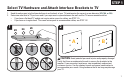
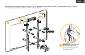
STEP 1 Select TV Hardware and Attach Interface Brackets to TV 1. 2. 1 Hand thread screws into the threaded inserts on the back of your TV to determine the correct screw diameter (M5, M6, or M8). Determine what kind of TV you have and if you require extra space between the wall and the TV to accommodate cables.
STEP 1-A Ensure that your brackets are level on the back of the TV. If you need extra space to accommodate cables, recesses, or protrusions; use spacers (see the irregular back option on the next page). A 01 02 09 10 03 04 05 IMPORTANT: After attaching the brackets, adjust the straps so they are level with the bottom of the TV.
STEP 1-B Ensure that your brackets are level on the back of the TV. Standard configurations are shown. For special applications, or if you are unsure about your hardware selection, contact Customer Service. B 01 02 11 09 10 06 07 08 IMPORTANT: After attaching the brackets, adjust the straps so they are level with the bottom of the TV.
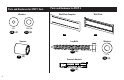
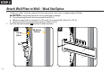
STEP 2 Attach Wall Plate to Wall - Wood Stud Option 1. 2. Locate your stud(s). Verify the center of the stud using an awl, a thin nail, or an edge to edge stud finder. CAUTION: Avoid potential personal injuries and property damage! ● Drywall covering the wall must not exceed 16 mm (5/8 in.). ● Minimum wood stud size: common 51 x 102 mm (2 x 4 in.) nominal 38 x 89 mm (1½ x 3½ in.). ● Minimum horizontal space between fasteners: 406 mm (16 in.) Level the wall plate template 12 and mark the hole locations.
STEP 2 3. Drill pilot holes. IMPORTANT: Pilot holes must be drilled to a depth of 75 mm (3 in.), using a 5.5 mm (7/32 in.) diameter drill bit. 4. Tighten the lag bolts 14 only until the washers 15 are pulled firmly against the wall plate 13 . CAUTION: Improper use could reduce the holding power of the lag bolt. DO NOT over-tighten the lag bolts. 3 4 75 mm (3 in.) 12 13 5.5 mm (7/32 in.
STEP 2 Attach Wall Plate to Wall - Solid Concrete or Concrete Block Option 1. 2. Level the wall plate template 12 and mark the hole locations. CAUTION: Avoid potential personal injuries and property damage! ● Mount the wall plate 13 directly onto the concrete surface ● Minimum solid concrete thickness: 203mm (8 in.) ● Minimum concrete block size: 203 x 203 x 406 mm (8 x 8 x 16 in.) ● Minimum horizontal space between fasteners: 406 mm (16 in.) Drill pilot holes.
STEP 2 3. Insert anchors 16 . CAUTION: Be sure the anchors are seated flush with the concrete surface. 4. Tighten the lag bolts 14 only until the washers 15 are pulled firmly against the wall plate 13 . CAUTION: Improper use could reduce the holding power of the lag bolt. DO NOT over-tighten the lag bolts.
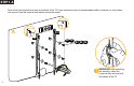
STEP 3 Attach TV to Wall HEAVY! You may need assistance with this step. 01 02 01 02 13 13 IMPORTANT: You will hear an audible click when the TV brackets are securely fastened to the wall plate.
Troubleshooting ADJUSTING THE LEVEL: If needed, tighten one of the screws on the top of the TV bracket to level the TV. REMOVING THE TV: Pull down on the straps and lift the TV up and out away from the wall plate.
ESPAÑOL INSTRUCCIONES DE SEGURIDAD IMPORTANTES. CONSÉRVELAS. LEA TODO EL MANUAL ANTES DE UTILIZAR ESTE PRODUCTO.
ESPAÑOL Piezas y elementos de sujeción suministrados ADVERTENCIA: Este producto contiene piezas pequeñas que, si fuesen tragadas, podrían producir asfixia. Antes de iniciar el ensamblaje, compruebe que todas las piezas estén incluidas y en buenas condiciones. Si faltan piezas o alguna está dañada, no devuelva el artículo al distribuidor; póngase en contacto con el servicio de atención al cliente. Nunca utilice piezas deterioradas. NOTA: No todos los elementos de sujeción incluidos deberán utilizarse.
ESPAÑOL PASO 1-B Asegúrese de que las placas de sujeción quede nivelada en la parte posterior del televisor. Se ilustran las configuraciones estándar. Si desea información sobre aplicaciones especiales o si tiene dudas sobre la selección de piezas, contáctese con el servicio de atención al cliente. IMPORTANTE: Luego de fijar las placas de sujeción, ajuste las correas para nivelarlas con la parte inferior del televisor. PASO 2 Fijar la placa mural a la pared - Opción para montantes de madera 1.
ESPAÑOL 2. ● Tamaño mínimo del bloque de cemento: 203 x 203 x 406 mm (8 x 8 x 16 pulgadas) ● Espacio horizontal mínimo entre los elementos de sujeción: 406 mm (16 pulgadas) Realice los orificios guía. IMPORTANTE: Los orificios deben realizarse con una mecha de 10 mm (3/8 pulgada) de diámetro, hasta una profundidad de 75 mm (3 pulgadas). Nunca perfore el cemento que une los bloques. 3. Inserte los anclajes 16 .
Thank you for choosing Sanus VuePoint! Please take a moment to let us know how we did: Call us: 888-333-9952 Email us: info@sanus.com Leave a review: vuepoint.sanus.com UK: 0800 056 2853 Milestone AV Technologies and its affiliated corporations and subsidiaries (collectively, “Milestone”), intend to make this manual accurate and complete. However, Milestone makes no claim that the information contained herein covers all details, conditions, or variations.