FPA400 INSTRUCTION MANUAL We’ll Make It Stress-Free If you have any questions along the way, just give us a call. 1-888-333-9952. We’re ready to help! Scan for easy install video san.
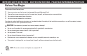
IMPORTANT SAFETY INSTRUCTIONS – SAVE THESE INSTRUCTIONS – PLEASE READ ENTIRE MANUAL PRIOR TO USE Before You Begin Please check the following items: Any accessories you plan to use do not exceed the specified weight limit. The wall you chose to mount your shelf is wood stud, drywall, solid concrete, or concrete block. You read and understand these directions. You have the tools needed for installation.
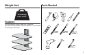
Weight Limit Tools Needed 15 lb (6.8 kg) DO NOT EXCEED! Features Can be mounted to drywall, wood stud, or concrete. Stackable to accommodate multiple components - not to exceed 15 lb (6.8 kg) on each shelf. 3 mm (1/8 in.) 10 mm (3/8 in.) 10 mm (3/8 in.) 11 mm (7/16 in.
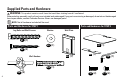
Supplied Parts and Hardware WARNING: This product contains small items that could be a choking hazard if swallowed. Before starting assembly, verify all parts are included and undamaged. If any parts are missing or damaged, do not return the damaged item to your dealer; contact Customer Service. Never use damaged parts! NOTE: Not all hardware included will be used. Parts and Hardware for STEP 1 Lag Bolts and Wall Screws 1/4 x 2 ½ in.
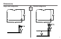
Dimensions Single shelf configuration in. [mm] Stacked configuration 12.50 317.5 12.50 317.5 17.00 431.8 17.00 431.8 1.11 28.1 1.11 28.1 6.3 159.9 6.3 159.9 5.11 129.
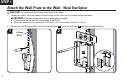
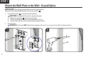
STEP 1 Attach the Wall Plate to the Wall - Wood Stud Option 1. 2. IMPORTANT: For stacking configurations, stack from the top down. Locate your stud(s). Verify the center of the stud using an awl, a thin nail, or an edge to edge stud finder. CAUTION: Avoid potential personal injuries and property damage! ● Drywall covering the wall must not exceed 16 mm (5/8 in.). ● Minimum wood stud size: common 51 x 102 mm (2 x 4 in.) nominal 38 x 89 mm (1½ x 3½ in.).
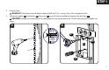
STEP 1 3. Drill pilot holes. IMPORTANT: Pilot holes must be drilled to a depth of 63.5 mm (2½ in.), using a 3 mm (1/8 in.) diameter drill bit. 4. Tighten the lag bolt 01 and washer 03 the screw 02 only until they are pulled firmly against the wall plate 06 . CAUTION: Improper use could reduce the holding power of the lag bolt and screw. DO NOT over-tighten the lag bolt and screw. 3 4 63.5 mm (2½ in.) 01 3 mm (1/8 in.
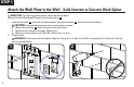
STEP 1 Attach the Wall Plate to the Wall - Solid Concrete or Concrete Block Option IMPORTANT: For stacking configurations, stack from the top down. Remove the front (F) and top (T) covers from the wall plate 06 . 1. 2. Level the wall plate 06 and mark the hole locations. Level the wall plate 06 and mark the hole locations. CAUTION: Avoid potential personal injuries and property damage! ● Mount the wall plate 06 directly onto the concrete surface ● Minimum solid concrete thickness: 203mm (8 in.
STEP 1 3. Insert anchors 04 and 05 . CAUTION: Be sure the anchors are seated flush with the concrete surface. 4. Tighten the lag bolt 01 and washer 03 the screw 02 only until they are pulled firmly against the wall plate 06 . CAUTION: Improper use could reduce the holding power of the lag bolt and screw. DO NOT over-tighten the lag bolt and screw.
STEP 1 Attach the Wall Plate to the Wall - Drywall Option IMPORTANT: For stacking configurations, stack from the top down. Remove the front (F) and top (T) covers from the wall plate 06 . 1. Level the wall plate 06 and mark the hole locations. CAUTION: Avoid potential injuries or property damage! ● ● ● 2. Mount the wall plate 06 directly onto the wall. Drywall covering the wall must not exceed 13mm (1/2 in.). Do not install anchors into the seam between drywall pieces. Drill pilot holes.
STEP 1 3. Insert anchors 04 . CAUTION: Be sure the anchors are seated flush with the surface. 4. Tighten the screws 02 only until they are pulled firmly against the wall plate 06 . CAUTION: Improper use could reduce the holding power of the screw. DO NOT over-tighten the screws.
STEP 2 Attach Glass to Wall Plate 1. Slide the glass shelf 07 into the wall plate 06 . Line up the holes in the shelf to the holes in the wall plate as shown. 2. Secure the glass shelf 07 to the wall plate 06 using screws 10 . 3. Attach the safety plate 08 to the glass shelf 07 using screws 11 .
STEP 3 Manage Cables Single shelf configuration Cables can be routed through the opening in the lower back of the wall plate 06 . Stacked configurations For stacked configurations, cables can be routed through the inside of the wall plates 06 . When you are done routing cables replace the top (T) and front (F) covers.
ESPAÑOL INSTRUCCIONES DE SEGURIDAD IMPORTANTES. CONSÉRVELAS. LEA TODO EL MANUAL ANTES DE UTILIZAR ESTE PRODUCTO. Antes de comenzar Cerciórese de: que los accesorios que planifica usar no excedan el límite de peso especificado; que la pared escogida para el montaje de su repisa sea una pared de montantes de madera, yeso, hormigón sólido o bloques de cemento; haber leído y comprendido estas instrucciones; tener todas las herramientas necesarias para la instalación.
ESPAÑOL Piezas y elementos de sujeción suministrados ADVERTENCIA: Este producto contiene piezas pequeñas que, si fuesen tragadas, podrían producir asfixia. Antes de iniciar el ensamblaje, compruebe que todas las piezas estén incluidas y en buenas condiciones. Si faltan piezas o alguna está dañada, no devuelva el artículo al distribuidor; póngase en contacto con el servicio de atención al cliente. Nunca utilice piezas deterioradas. NOTA: No todos los elementos de sujeción incluidos deberán utilizarse.
ESPAÑOL Fijar la placa mural a la pared - Opción para hormigón sólido o bloques de cemento IMPORTANTE: Para las configuraciones apiladas, comience a apilar de arriba a abajo. Retire las cubiertas frontal (F) y superior (T) de la placa mural 06 . 1. Nivele la placa mural 06 y marque la ubicación de los orificios. Nivele la placa mural 06 y marque la ubicación de los orificios. 2. 3. PRECAUCIÓN: Evite posibles lesiones personales y daños materiales.
ESPAÑOL 2. Realice los orificios guía. IMPORTANTE: Los orificios guía DEBEN realizarse con una mecha de 10 mm (3/8 pulgada) de diámetro hasta una profundidad de 38 mm (1½ pulgadas). 3. Inserte los anclajes 04 . PRECAUCIÓN: Cerciórese de que los anclajes hayan quedado nivelados respecto de la superficie. 4. Ajuste los tornillos 02 solamente hasta que queden firmes contra la placa mural 06 . PRECAUCIÓN: El uso indebido podría reducir la capacidad de retención del tornillo. NO ajuste en exceso los tornillos.
Thank you for choosing Sanus VuePoint! Please take a moment to let us know how we did: Call us: 1-888-333-9952 UK: 0800 056 2853 Email us: info@sanus.com Find us on Facebook: SANUS Leave a review: vuepoint.sanus.com Follow us on Twitter @sanussystems Milestone AV Technologies and its affiliated corporations and subsidiaries (collectively, “Milestone”), intend to make this manual accurate and complete.