Warning This equipment generates and uses radio frequency energy. If it is not installed and used properly, that is, in strict accordance with the manufacturer's instructions, it may cause interference to radio and television reception. It has been tested and found to comply with the limits for a Class B computing device in accordance with the specifications in Subpart J, Part 15, of FCC Rules. These rules are designed to provide reasonable protection against such interference in a residential installation.
Copyright This manual is copyrighted with all rights reserved. No portion of this document may be copied or reproduced by any means without the prior consent in writing from Video Technology Computers, Inc. While every precaution has been taken in the preparation of this book, Video Technology assumes no. responsibility for errors or omissions. Neither is any liability assumed for damages resulting from the use of the information contained herein. © Copyright 1988 by Video Technology Computers, Ltd.
Table of Contents Chapter 1: Installation ................................................................ 5 Introduction .................................................................................... Preparing for the Installation .................................................. Checking the Contents of the Package .............................. Hardware Features Overview .................................................. Connecting Peripherals ......................................................
Chapter 4: Enhancements .......................................................... 43 Special Note .................................................................................. Opening the System Unit ........................................................ Road Map of Internal Components .................................... Expanding System Memory to 640KB ................................ Installing Parity RAM .............................................................. Installing Expansion Cards ..
Chapter 1: Installation Introduction The computer is a high performance, expandable personal com puter system which is designed specifically to be compatible .with software and peripherals conforming to the popular MS DOS and mM PC-XT standard. In some versions of the computer there may be differences in memory size and expansion cards installed, you may need to refer to a separate user's manual for any other expansion card installed. • IBM PC/XT compatible processor running at 4.77 or 10 MHz.
• Socket for an Intel 8087 math co-processor • Eight expansion slots In this fIrst chapter, we will guide you through the installation of the computer, and introduce you to the basic structure of the computer. If you are unfamiliar with the meaning of a cer tain term, you can consult the glossary in Appendix 4 for a definition.
Preparing for the Installation Before you install the computer, you should have a large clear area on which to work. Clear a tabletop large enough to hold the system unit and keyboard. The monitor can sit on top of the system unit if space is at a premium. You will need the following: • A grounded, three-prong power outlet • A small flathead screwdriver These tools are sufficient for a normal installation.
Checking the Contents of the Package Carefully unpack the computer from its carton. Make sure the carton contains the following: • The computer system unit • A keyboard • A power cord • A video cable for composite monitors • A package with manuals for MS-DOS®and GW/BASIC ®(optional) • A package containing four diskettes • A warranty card It is important to save the carton and packing materials in case you need to ship your unit in the future. Be sure to return the warranty card as soon as possible.
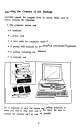
Hardware Features Overview With the computer on a level surface, examine the following features on the front panel: Keyboard lock/unlock LED indicators "B" Space reserved for hard When the security lock is switched at left position, keyboard is unlocked and reset button is enabled; with the lock switched at right position, keyboard is locked and reset button is disabled.
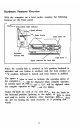
Diskette are On the right side panel, you'll find the ON-OFF switch. The "1" setting means "ON", and "0" means "OFF". On the back side, there are several important connectors. You should notice: Monochrome monitor EGA card DIP switch eGA, monochrome or EGA monitor Toggle switch For composite monochrome monitor Monochrome graphics/Color graphiCS card In normal installations, there is no need to open the system cabinet.
Connecting Peripherals 1. Before connecting anything to your computer, make sure the power is off. The switch on the right panel should be in the down, or "0" position. 2. If you haven't done so already, remove the keyboard from its protective plastic bag. The keyboard cable attaches into the rounded five-pin socket on the back of the main unit: -r ~/ 0 Make sure the plug is lined up with the socket. The small indentation should be pointing upwards. 3.
6. Insert the main power cable that comes with the computer into the socket on the back of the system unit. , Plug the other end into a grounded, three-prong wall outlet. 7. Flip up the levers on the two floppy disk drives, and remove the sheets of cardboard that protect the drives during shipping. Remember to save these cards with the rest of the packaging.
Starting the Computer For system installed with hard disk, please follow the proce dure: 1. Turn on the power to your monitor. The ON/OFF switch IS normally found on the front of the video. screen. 2. Turn on the power to the system unit by flipping the red power switch on the right side into the up position, labeled "1". 3. During the start-up procedure, the system performs a mem ory test, then loads the MS-DOS operating system.
If your computer has no hard disk drive installed, then follow the following procedures: Open the package of diskettes that came with the system. Locate the diskette labeled "Microsoft MS-DOS." Insert the diskette into the floppy drive with the label side up. The oval opening in the diskette should go in first. When the diskette is all the way into the drive, close the latch by moving the lever into the down position. Then performs step 1 to step 3 as described above.
Setting the System Clock Your computer has its own clock to keep track of the date and time while you work. The clock is not set in the factory, so you'll need to set it the first time you use it. 1. The Computer Main Menu (As shown on page 9) should appear on the screen. 2. Type in the letter "K" . MS-DOS treats upper and lower case letters the same way, so it doesn't matter whether you're using capital or small letters. 3. The system will display the current date.
Operation Speed The computer can operate at two different speeds. Some software requires you to operate at 4.77 MHz to maintain full compatibility with the original IBM PC-XT. When possible though, you should try to operate your computer at the "turbo speed" of 10 MHz. After warm or cold start, your computer will operate at 4.77MHz. For 4.77MHz Operation: Press ~ and I~ I simultaneously. For 10 MHz Turbo Operation: Press ~ and ~ simultaneously.
Chapter 2: Using the Keyboard The Keyboard Security Lock The computer features a keyboard lock on the front panel. With the keyboard locked, no characters can be typed in to the computer, protecting your system from unwanted intruders. You receive two keys with the unit. Make sure you store one in a safe place. Two LEDs are used to indicate whether the keyboard is locked or unlocked. For example, when the keyboard is locked, the LED labelled with 'keyboard lock' will be on.
Overview The keyboard is your primary means of communicating with your computer. Its layout roughly resembles an ordinary type writer. To describe the keyboard clearly, its helpful to divide it into four parts, each with its own function.
The Typewriter Keys The typewriter area of the keyboard behaves a lot like a standard keyboard. Like a typewriter, the SHIFT key produces capital letters. To type the special characters shown above the numbers on the number keys, hold down the SHIFT key and press the appropriate key. For example, the SHIFT key with the number 1 produces an exclamation mark (!).
ENTER... As a RETURN key, it ends the line being typed and advances to the next line. As the ENTER key, it's used to execute commands you have typed. 10 SHIFf... For upper case letters, punctuation, or Shift symbols, either one of the two SHIFT keys can be pressed. When the CAPS WCK key is engaged, the SHIFT key acts as an "Un-Shift" key, allowing you to type lower case letters. EJ BACKSPACE... Like the Backspace key on a typewriter, it will erase one character to the left of the cursor.
CTRL-PRINT SCREEN...ECHO The computer prints each line as it is typed. To cancel the function, press CTRL-Print SCREEN again. CTRL-NUM WCK. ...PAUSE This temporarily halts printing or a screen display. Press any key to continue. CTRL-ALT-DEL.. ..sySTEM RESET When these three keys are pressed together, the system resets and reloads the operating system. ALT... Like the CTRL key, ALT performs no function on its own. It is used in conjunction with other keys to perform special functions.
The Numeric Keypad The numeric keypad, shown below, performs a dual function. With the NUM LOCK key engaged (indicated by the status light in the upper right and corner of the keyboard), the keypad is useful for the rapid data entry of numbers. Without NUM LOCK, the keypad can be used to move the cursor or do special editing features. The 102 key enhanced keyboard provides a separate keypad for cursor control and editing (located immediately to the left of the numeric keypad).
+...Displays the PLUS symbol. + D -...Displays the MINUS symbol. • ...Displays the ASTERISK, used for multiplica tion. j ...Displays the SLASH, used for division. These keys behave differently depending on the status of the NUM LOCK key: NUM LOCK ON NUM LOCK OFF The number 1 END... Moves the cursor to the end of the line. [] The number 2 Moves the cursor down. The number 3 PG DN... Moves the cur sor down one page, or 25 lines. The number 4 Moves the cursor left.
[g The number 6 Moves the cursor right. I~omel The number 7 HOME... Moves the [] The number 8 Moves the cursor up. I~upi The number 9 PG UP... Moves the I~ns I The number 0 I~el I cursor to the screen's upper left hand corner. cursor up to the beginning of a page. INS... (Insert) Turns on "insert mode." Characters typed are inserted before text that already exists. DEL••• (Delete) Erases one character at the position of the cursor.
Editing and Cursor Control Keys This keypad sits between the Typewriter and Numeric keypads. It performs the same functions as the keys on the Numeric keypad with the NUM LOCK key off: 6 [!J [] EJ H 0 ME... Moves the cursor to the first charac ter in the upper left hand corner of the screen. CURSOR UP... Moves the cursor up one line. CURSOR DOWN... Moves the cursor down one line. CURSOR RIGHT ... Moves the cursor one character to the right. EJ CURSOR LEFr... Moves the cursor left one EJ END...
DELETE... Deletes one character at the position of the cursor. All characters move left one position to fill in the deleted character. INSERT... Turns on the "insert mode." Char acters you type will be inserted before text that already exists, pushing the existing text to the right. With insert mode off, characters to the right are overwritten. I I I I Page Up Page On PAGE UP/PAGE DOWN... Its functions arc defined by the application you are using.
Function Keys Located along the top half of the keyboard, these twelve function keys allow you to perform complex commands with a single keystroke. Most applications use function keys for different purposes. When running the MS-DOS operating system, the function keys per form the following activities: FI... Copies one character from a temporary storage area to the display. Each time you enter a command, MS-DOS store the command in a temporary storage area. EJ EJ EJ EJ Fl...
28
Chapter 3: Introduction for New Users Facts You Should Know This chapter is intended for people with no computing experi ence. If you fall into this category, we hope you'll find some of the concepts introduced here to be helpful. Let's start with a few general facts: • A computer is not like a television set that you can simply take out of the box and plug in. It will require both time and patience to learn. If you try to learn things too quickly under pressure, you may get frustrated.
Introduction to MS-DOS MS-DOS stands for MicroSoft Disk Operating System. An operating system is a group of programs that acts as: • A manager for your computer, monitor, and peripherals • An interpreter, conveying your instructions to the computer If you plan on running application programs only (software written to perform specific tasks, e.g. Lotus 1-2-3®or WordPer fect), you actually need to know very little about the MS-DOS operating system.
Storing Files on a Computer To learn more about how your computer works, you have to learn how MS-DOS organizes and stores data. All information on disks is stored in fi1es. A fIle is simply a collection of information. Computer fIles can be broken down into three categories: • System Files... contain MS-DOS information that man ages the computer operations. • Program Files... contain information that lets your computer perform a series of specific tasks. • Data Files...
Organizing Files into Directories Files on a disk are grouped into directories. A directory is simply a "Table of Contents" for the disk. For each file residing on a disk, an entry is made in a directory recording the name of the file, its size, and its location on the disk, data of creation, attributes. Every disk contains one main directory called the root directory. The root directory serves as a "master index" for the disk.
ROOT I FINANCE I I LETTERS I Budget Checkbk Bills OFFICE SlsDept Acctg Thank You Filel File2 PERSONAL AuntMary Janice The rules for naming directories are the same as those for naming fIles. Names can be up to eight characters long, and contain letters, numbers, and the symbols $ & # % ' ( ) @ or 1.
The Menu of MS-DOS Activities The computer features a helpful menu of the most common MS-DOS commands. The menu appears whenever you start up the machine: LASER TURBO XT Start Up Utility Main Menu [A] Format a disk [B] Format a sys disk [C]Format hard drive [D] Copy file (s) [E] Copy disk [F] Make a directory [G]Remove directory [H]Change directory [I]Display directory [J]Run a program [K)Change date &time [L]Check config.
Command Function [A] Format a disk Prepare a new, blank diskette for use on your system. You must have the file FORMAT.EXE in the current directory. ·Doyou have FORMAT.EXE in the current directory (Y or N)? 'Enter the drive letter for format (A: - D:) [B] Format a sys disk Creates a diskette capable of being used as a system start-up disk. *Doyou have FORMAT.
Command Function [E] Copy disk Copies the contents of a diskette in disk drive "A" to a diskette in drive "B". You must have the file DISKCOPY.EXE in the current directory. ·Doyou have DISKCOPY.EXE in the current directory ('l or N)? [F] Make a directory Creates a new directory or subdirectory. ·Enter the name for the new directory. [G] Remove directory Deletes a directory from the disk. The directory must be empty of files before it can be removed.
Command [L] Check config. Displays details about your system configuration (i.e. how many drives, how much memory). *Doyou have WHATAMI.EXE in the current directory (Y or N)? [M] Display help me Prints a copy of the help file pertaining to these menu selections. in the current directory (Y orN)? [N] Exit to DOS Ends this Menu Program and returns you to the standard DOS prompt. To restart the menu program, enter MENU at the DOS prompt.
How to Care for Your Computer 1. Until you gain a great deal of experience, do not attempt to probe the inside of your computer, particularly the power supply. Dangerous levels of high voltage exist. Contact your dealer for service if necessary. 2. Turn off the computer and unplug it from the wall before you install anything inside the system unit, such as an ex pansion card or memory chips. Failure to do so will result in serious, irreparable damage to both the computer and the add-on device. 3.
Diskette Care The 5-1/4" Floppy Disk Drive of the computer uses 5-1/4", double sided, double density (40 tracks per inch), soft sectored floppy diskettes. These diskettes are capable of holding 360K (368,640 bytes). Each floppy diskette has a write-protect notch on its side, as shown in this diagram: If this notch is covered, the computer will not let you write to the diskette. This is a good way to make sure no one erases diskettes that are absolutely crucial.
• Never lay a diskette on top of or next to the computer system unit. • Write only on a diskette label, and only with a soft felt tip pen. Never use a ball point pen to write on diskettes. • Keep diskettes out of direct sunlight and away from excessive heat. They melt easily. • Some versions of the computer has a 720K 3 1/2" Floppy disk drive installed. These drives use 3 1/2" Floppy diskettes: which are capable of holding 720K bytes maxi mally.
Hints on using 3-1/2" drive Before you are going to use the 3-1/2" drive, there are some basic concept and terminology you need to know. A physical drive is a drive that is physically connected to the computer. A logical drive is a drive that can be accessed through the "drive letter" assigned, e.g. A:, B:. Thus there may be more logical drives than physical drives, since two or more logical drives may refer to the same physi cal drive. An external drive is the drive that is created by the" file CONFIG.
3. Warm boot the system. 3.5" disks can now be formatted on nOKB. (B) If you are using DOS 3.3 1. Insert a DOS disk which contains the DRIVER.SYS into drive A. 2. If your 3.5" disk drive is the second drive, create the CONFIG.SYS file and include the follow line: device = driver.sys/d:l This line tells the system to install an external drive C:. The parameter /d:l specifies that the external drive C: is logically linked to the second physical drive B:.
Chapter 4: Enhancements Special Note The enhancements described in this chapter let you improve the power and performance of your computer system. The parts required for each enhancement are available from your dealer. All these enhancements require you to open the system unit and install add-on accessories inside. Furthermore, some of the instructions may seem complicated, especially for first time computer users. If you are a new computer user, you ntay want to have your dealer install the enhancements.
Opening the System Unit To open the computer system unit, you'll need a Philips screwdriver. Begin by placing the computer system unit on a flat surface. Unplug the power cord from the wall outlet! Looking at the back of the system unit, there are five screws you need to remove: Remove the screws and put them in a safe place. Grasp the cover of the chassis with both hands, and slide it forward and off, as shown below. There are several ribbon cables present in the system.
Road Map of Internal Components With the system unit open, this is a good time to get a general overview of the internal parts of the system unit: Notice the following areas of the system unit: • System Board • Expansion Slots • Hard Disk Controller • Multiple Input-Output (I-O) Card • EGA card • Floppy Drives "A" and 5 1/4", 360K • Floppy Drive "B" 3 1/2", nOK • Socket for an 8087 Math Co-Processor • Hard disk "c" • Power Supply • Sockets for Memory Expansion to 640K.
I lard disk controller card Power supply Sockets for memory expansion to 640K 4 empty rows for installing e:.
Expanding System Memory to 640K MS-DOS itself recognizes up to 640K of memory. Because the computer comes with 512K of memory, one of the fIrst en hancements we recommend is expanding the system memory to its full 640K. There are four simple tricks to successfully installing memory on the system board: 1. Purchase the correct memory chips. 2. Install the chips in the right place on the system board. 3. Make sure the chips are pointing the right way when you install them in their sockets. 4.
2. Install the chips in the right sockets on the system board. As shown in this diagram, the sockets for the four 4464 RAM chips are highlighted. The chips will be installed in sockets U36, U37, U38 and U39. =c::J====== === I ===I c::J c::=::J ~ ~~6 ==== ==== ==== ==== ==== 6 CJc], 12:3=g§3 =-CJ= u= ,= = c::::J c::::J -== _== -B§l ===., 3. Make sure the chips are pointing the right way. Take a careful look at the top of the memory chips.
You must install the new memory chips with the indentation facing the back of the system unit, in the exact same direction as the other memory chips. 4. Make sure none of the pins on the chip bend when you insert them into their sockets. Now that you know what kind of chips to use, where they go, and which direction they point, you are ready to actually install the RAM chips. With the chip facing the right direction, carefully place the prongs from the RAM chip into the holes on the socket. Press downward.
5. Set the switch on the system board so the computer recog nizes all 640K. The computer has banks of switches labeled SW1 and SW2. SWI is a bank switch having 8, small switches and SW2 is a bank switch having four small switches. Locate Switch Bank #1 (SW1) as shown in the diagram: E~~~O c:::::::J ~ c=::::J c=::::J Right now, switch 3 IS ON. To set your system to 640K of memory, turn switch 3 OFF. You can use the ~ip of a pencil or the head of a small screwdriver to move the switch.
Installing Parity RAM RAM parity is a method the computer can use to continually monitor and test the performance and reliability of the memory chips. The advantage of parity RAM is the error-checking it performs. Parity RAM spots potential failure in the RAM chips, and informs the user. Without parity RAM, your system may "lock up" if a failure occurs, providing no indication of the cause of the failure. The disadvantage of parity RAM is its cost.
3. Make sure the chips are pointing the right way. As before, notice the indentation on the chips is pointing towards the center of the system board (toward the back of the unit). Make sure you install the parity RAM with the chips pointing in the same direction. 4. Press the chips into place in their proper sockets. Once again, make sure no pins are bent or protruding from the socket. S. You'll need to adjust a jumper to tell the computer that parity RAM is now enabled.
To enable RAM parity, gently lift the jumper of the two pins it's on now, and place it on the two pins shown below. RAM Parity Enabled Jumper JP5 Jumper JP7 installed.
Installing Expansion Cards Installing expansion cards into slots is a very simple process. With six expansion slots free, you· have a lot of room to enhance the capabilities of your computer. 1. Before you begin: • Unplug the computer from the wall outlet. • Remember that circuit boards are sensitive to static elec tricity. Rid your hands of static electricity by touching the system chassis every time before touching a circuit board. 2.
3. Slide the card into place, with its tab meeting the grooves in the expansion slot. 4. Replace the slot cover screw, which will secure the endplate bracket of the card to the back of the system unit.
Installing an 8087 Math Co-Processor The computer has a socket available for an 8087 math co processor chip. This chip is specialized to do floating point arithmetic very fast. If you are working intensively with enormous spreadsheets or mathematics, it could speed "number crunching" significantly. It's manufactured by Intel, and should be purchased from an authorized Intel dealer. 1. Purchase the correct chip. Ask the dealer for an 8087-1 math co-processor.
3. Make sure the chip is pointing in the right direction. The notch on the 8087-1 should be pointing to the rear of the unit (towards the back panel). 4. Press the co-processor chip into place in its socket. Once again, make sure none of the pins are bent or protruding from the socket. 5. Set the switch on the system board so the computer recog nizes the 8087 math co-processor. Locate Switch Bank #1 (SW1) as shown in the diagram: ON ~~~~~~~~ 12345678 Right now, switch 2 is ON.
Installing Expanded Memory As mentioned before, MS-DOS only recognizes up to 640K of memory. Any memory above and beyond 640K is referred to as expanded memory. Some applications like Lotus 1-2-3 and Dbase III make use of up to 8 megaqytes (8 MB, or 8,192K) of expanded memory. On your computer system board, there is room for you to add one megabyte (1 MB) of expanded memory. You must add expanded memory in increments of 512K, so you can add 512K or 1 ME. As always, before you install anything, MAKE SURE .
The first 5i2K of expanded memory goes in Bank O. The first sixteen chips get installed in sockets U50 through U57, and U60 through U67. If you are using parity RAM, install another chip at U58 and U59. If you are installing 1 MB of expanded memory, fill up Bank 1. Remember, the socket at U76 and U77 need to be filled only if you are using RAM parity-checking. 3. Make sure the chips are pointing the right way.
Using Expanded Memory As mentioned previously, MS-DOS does not recognize any memory past 640K. All memory over 640K is called expanded memory. Some software packages are written to automatically recognize expanded memory. For example, Lotus 1-2-3 and Microsoft Windows 2.0 take full advantage of expanded memory. Other programs will not recognize expanded memory at all. It depends specifically on the application you are using. We have supplied two software programs which are used with your expanded memory.
ERAMDISK.SYS This is a driver to turn your expanded memory into a RAM disk. A RAM disk program sets aside a portion of memory and treats it as if it were a physical disk drive. In other words, with two floppy disk drives on your system (Drive "A" and "B"), the RAM disk becomes Drive "C". If you also have a hard disk installed, the RAM disk becomes Drive "D". • To use S12K of expanded memory as a RAM disk, the following line must appear in CONFIG.SYS: DEVICE = ERAMDISK.
Installing a Hard Disk Drive If your computer is equipped with a hard disk drive, you will need to prepare the disk for use by "formatting" it. Follow these simple instructions: 1. The Start-Up Utility Main Menu (As shown on page 9) should appear on the screen. 2. Type in the letter "C". This option formats your hard disk drive. This should only be done once when the disk is first used. This option completely erases all information on the hard disk, so be careful when running this option. 3.
Chapter 5: Trouble Shooting Checklist Symptoms and Suggestions Symptom Suggestions No response from the main unit. • The ON/OFF switch should be in the ON or "I" position. • Make sure the outlet itself works. • The power plug may be improp erly connected to the back of the system unit. No screen display. • Monitor cable is not properly con nected to the Monochrome Graph ics/Color Graphics Card • Monitor power cable is not plugged in properly • The monitor's power switch 18 not turned on.
Symptom Suggestions No response from the keyboard. • Keyboard cable not properly connected. Check to make sure it's plugged in properly on the back of the system unit. • System crash. Restart your system using the reset button on the back of the system unit. If neces sary, turn your unit off, then on again. • Keyboard lock is not off. Disk drive error. • Latch on the disk drive is not closed properly. • The diskette was not placed in the drive correctly.
Beeps 1 Long + 1 Short Base 64K RAM isn't usable. Check the RAM chips. 1 Long + 2 Short The video selector switch on the Monochrome Graphics/ Color Graphics Card isn't properly set. 1 Long + 5 Short BIOS ROM checksum IS incorrect. Replace the BIOS chip.
Display Messages Message Cause & Suggested Solution Video error. • BIOS couldn't find the type of display adapter requested by the switch settings. • Check the DIP switches and switch on the Monochrome Graph ics/Color Graphics Card Keyboard Error 0100. • Keyboard did not respond. • Check the connector on the key board. Keyboard Error 02XX. • Keyboard returned the wrong test code xx. • Replace the keyboard. Keyboard Error 04XX. • Keyboard interrupt would not clear.
CHAPTER 6: Further Reading There are many popular books on the market written about IBM PC-XT Compatible computers and the MS-DOS Operating System. Whether searching for a good tutorial for beginners or an advanced reference manual for experts, you can certainly fmd a book geared toward your specific needs. Here is a partial list of books available in retail stores or public libraries. There are hundreds of other relevant books m print. Consult your local library for a more complete listing.
Other books available from computer retailers and book stores include: Quick and Easy PC-DOSjMS-DOS, Alfred Publishing Company, Inc. Your IBM-PC Made Easy, Osborne/McGraw-Hill Your IBM: A Guide to the IBM-PC, OsbornejMcGraw-Hill Learning DOS, Microsoft Corporation How to Use Your IBM-PC, American Training Interna tional Teach Yourself PC-DOS, American Training International.
Appendix 1: Dip Switches and Settings Switch Box #1 (SW1) Position 1: Diagnostics ~ooooooo 12345678 ~ooooooo Normal operation Factory testing only Position 2: 12345678 8087-1 Math Co-Processor TI~oooooo D~oooooo 12345678 Without 8087 co-processor 12345678 With 8087 co-processor Position 3 Conventional Memory Amount ~o~ooooo 12345678 TIo~ooooo 512K conventional Memory 640K conventional Memory Installed Position 4 12345678 Not Used 69
Position 5 & 6: Type of Display ON ~~~~~~~~ Enhanced Graphics Adaptor or Video Graphics array (VGA) 12345678 ON DD~~~~~~ Color graphics adaptor 40 x25 mode 12345678 Color graphics adaptor 80x25 mode Monochrome display adaptor or Hercules graphics card Position 7 & 8: Floppy Disk Drives ON n~~m~~~ oooo~o~~ 12345678 12345678 Two (2) floppy drives One (1) floppy drive 12345678 ~~~m~~~ Three (3) floppy drives Four (4) floppy drives 12345678 70
Switch Box #2 (SW2) Switch SW2 is used for setting the I/O Port address for the expanded memory installed in the computer. If you have up to one megabyte of expanded memory, the settings are easy. The position of switches 1, 2 and 3 on SW2 determine the o port address of the expanded memory.
72
Appendix 2: The Multi I/O Card The multifunction input/output (Multi I/O) card installed ill the computer gives you several powerful features packed into a single expansion card. You get: • Centronics Parallel Printer Port • RS232C Serial Port • Joystick Port • A Real-Time Clock • Floppy disk interface On the Multi I/O Card, you'll [rod two jumper blocks. Jumper JPl is used for setting the interrupt request levels for the real time clock. In reality, you should never have to change the setting of JPl.
Notice how the jumpers are set when the unit leaves the factory: 25 • • • • • • • • • 1 27~~~~~~~~~ 3 IHGFEDCBA The letters under each row are for illustration only. They do not actually appear on the jumper block.
Row D: Serial Port COM2 The Multi I/O card normally has only one serial port named COMl. If you wish to purchase additional hardware, you can add a second serial port named COM2. Contact your dealer for details.
Parallel Printer Port Used for connecting a parallel printer with Centronics standard input. It is fully compatible with the IBM PC-XT parallel printer port.
RS232 Serial Port Used for connecting a serial printer or modem with RS232 standard input. It is fully compatible with the IBM PC-XT serial port.
Joystick Port Used for connecting a joystick mechanism to the Laser Turbo XT using a is-pin "D" style connector. r -xc~;din-;t;- -, +5V I I I 1 Switch 4 r' I X I r 1 1 9 ~-1 , d' oor onate r y r I~Vr--------l I 2 I 10 I 3 '1 4 I 12 lye I " 13 5 I r Gnd I I Y I Iy Coord.nate r I r l_____ jl2Jrt~~:11IL~-----J -. , .
Appendix 3: Monochrome Graphics /Color Graphics Card Overview As a color graphics adapter, this card provides a flexible interface to RGB monitors, as well as color and monochrome composite monitors. Graphic resolutions of 320 x 200 or 640 x 200 are available. When selected for monochrome operation, the Monochrome Graphics/Color Graphics Card is fully compatible with the Hercules graphics card, providing 720 x 348 resolution.
Using the Adapter in Non-Laser Computers If you install the Monochrome Graphics/Color Graphics Card in a non-Laser computer, or the Monochrome Graphics/Color Graphics Card coexists with another graphics card (e.g. EGA, CGA or MDA). You may have to disable the Laser BIOS built in to the graphics card. When you disable the built-in BIOS, you will need to set the DIP switches inside the non-Laser computer to match the MDA/CGA slide switch on the card's faceplate. To disable the built-in BIOS: 1.
With the jumper set in this manner, the BIOS on the Mono chrome Graphics/Color Graphics Card is disabled. If your Laser computer is installed with EGA card, please refer to user manual provided for the EGA card: If your Laser computer is installed with hard disk controller card please refer to the user manual provided for the hard disk controller.
82
Appendix 4: Glossary of Computer Terms As with any industry, the computer world seems to have a language all its own. Listed below are some of the most common words and phrases you will see in relation to personal computers. 8087 Coprocessor The 8087 is a computer chip designed to work with the computer's main microprocessor. The 8087 chip is designed specifically to speed up mathematical calculations for large spreadsheets, etc. 8086 The 8086 is a main microprocessor chip.
AT Style Keyboard IBM has manufactured a few different models of personal computers (PC, PC JR., PC/XT, PC/AT). The PC/AT style keyboard is generally considered to be superior. The AT style keyboard is designed to feel like an IBM Selec tric typewriter and has large SHIFf and RETURN keys. It is often said that the AT style keyboard feels more com fortable and is easier to work on because of its features. BIOS BIOS stands for Basic Input/Output System.
Bracket Brackets are the narrow metal pieces which cover the eight holes on the back of your computer. The eight holes correspond to the eight expansion slots in your computer. Brackets are used for two main purposes: one, they help anchor expansion cards securely; and two, they cover the openings for empty expansion slots so that dust and dirt can not enter your computer and damage it. CGA CGA stands for Color Graphics Adaptor.
DIP Switch The DIP in DIP switch stands for Dual In-line Package. DIP switches on your computer must be turned either "on" or "off' in order to tell your computer some very basic information. The main DIP switches inform the computer how much memory is installed, how many floppy disk drives there are, etc. The computer uses this critical information to test and orient itself every time the power is turned on. If a DIP switch is set incorrectly, your computer may not function properly.
Expansion Card An expansion card is a device you plug into a computer which allows you to add new features. Expansion cards are delicate electronic instruments, and should be handled with care. Expansion cards come in a variety of sizes(7", 10", and even full length 14" sizes ). Expansion cards are inserted in your computer's expansion slots. At the bottom of each expansion card you will find a 62 "gold fingered" band (31 gold stripes on each side).
Formatted Formatted diskettes are "mapped out". When you format a disk, the disk drive creates divisions ("sectors") on the diskette, and numbers them. With this, data that is saved on a formatted disk can be located in, say, sector 1, etc. Formatting gives your computer the ability to locate data with precise coordinates on each floppy diskette. Hard Disk Drive A hard disk drive (or fixed disk) can store much more information than a floppy disk drive.
I.C. Socket I.e. socket stands for Integrated Circuit socket. An I.C. socket is a location on the computer motherboard where you can insert a computer chip without soldering. Initializing Diskettes When you initialize a floppy diskette, you are "formatting" the floppy diskette. See fonnatted. LPT LPT is an abbreviation for computer parallel ports. Since computers can have more than one parallel port, parallel ports are always designated LPT1, LPTI, LPT3, etc.
Parallel Port Parallel ports are computer ports typically used for parallel Centronics printer hook-up. RAM RAM stands for Random Access Memory. You can read or write to RAM memory (versus ROM memory, which you can only read from). RAM memory is dynamic, you can change RAM memory contents by adding to or delet ing from RAM at your discretion. Re-Boot "Re-booting" your computer means to restart the computer from scratch.
ROM ROM stands for Read Only Memory. ROM memory is information your computer can readily access, necessary information. ROM memory differs from RAM memory in that you can not "write" or save information to the ROM memory locations. The only thing you can do to ROM memory is retrieve, or read, from it. Serial Port A computer serial port is typically labelled as a communi cations port.
Write Protect Every floppy diskette has a notch (or cut-out portion) on it. This notch allows the computer disk drive heads to write information onto the floppy disk. When you cover this notch, you can not write information onto the floppy disk. Write protect "tabs" are typically included with floppy diskettes when purchased so that you can use this safe guard measure for important data.