
User's Manual


V60G-HOME User Guide
Vayyar Confidential
Page
13
of
17
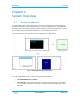
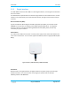
Figure 5: vBLU_OK _CTPB4 connector
The exact pinout is provided with the module itself and a reference design.
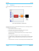
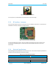
2.2.3 RF Interface - Antennas
The array of 46 antennas serves to connect the sensor unit with the environment. The antennas are
embedded in the PCB, as depicted in the figure below.
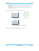
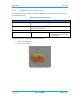
Figure 6: Antenna Positions and Numbering
For each transmitting (TX) antenna, there are multiple receiving (RX) antennas for collecting and
recording the received RF signals. Each RX antenna and its associated TX antenna serve as an
antenna pair.
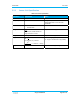
2.2.4 Electrical Specifications
The following electrical specifications are for the sensor unit. The current consumption specifications
are based on lab measurements performed by Vayyar.
Table 3: Sensor Unit Electrical Specification
Parameter Value
Vcc supply voltage 5 VDC
Max current consumption ~1.6 A
Average current consumption ~0.75 A