www.vscom.de User User Manual Manual USB-COM USB-COM USB-COM USB-COM PRO PRO Edition: Edition: June June 2009 2009 Tel: +49 40 528 401 0 Fax: +49 40 528 401 99 Web: www.visionsystems.de Support: service@visionsystems.
The software described in this manual is furnished under a license agreement and may be used only in accordance with the terms of that agreement. Copyright Notice Copyright © 2009 Vision Systems. All rights reserved. Reproduction without permission is prohibited. Trademarks VScom is a trademark of Vision Systems GmbH. All other trademarks and brands are property of their rightful owners. Disclaimer Vision Systems reserves the right to make changes and improvements to its product without providing notice.
Contents Contents 1 Overview 5 2 Introduction 2.1 Features . . . . . . . . . . . . . . 2.2 Product Specifications . . . . . . 2.2.1 VScom USB-COM PRO . 2.2.2 VScom USB-2COM PRO 2.2.3 VScom USB-4COM PRO 2.2.4 VScom USB-8COM PRO 2.3 Packing List . . . . . . . . . . . . 2.4 About this Manual . . . . . . . . . . . . . . . . . . . . . . . . . . . . . . . . . . . . . . . . . . . . . . . . . . . . . . . . . . . . . . . . . . . . . . . . . . . . . . . . . . . . . . . . . . . . . . . . . . . . . . . .
List of Tables 5.5 4-Wire Scheme . . . . . . . . . . . . . . . . . . . . . . . . . . . . . . . . . . . . . . . 29 6 Connector Definitions 30 6.1 DB9 male . . . . . . . . . . . . . . . . . . . . . . . . . . . . . . . . . . . . . . . . . . 30 6.2 DB25 male RS 232 . . . . . . . . . . . . . . . . . . . . . . . . . . . . . . . . . . . . . 31 6.3 Terminal Block . . . . . . . . . . . . . . . . . . . . . . . . . . . . . . . . . . . . . . .
2 Introduction 1 Overview The VScom USB-COM are serial port adapters, which are connected to the USB port. The VScom USB-COM PRO series are industrial strength devices, providing flexible serial ports. The ports may operate in RS232, RS422 or RS485 mode. This is completely configured by software, no jumpers or DIP switches are required. Further the USB-COM PRO come in a metal case of IP30, and provide the option for DIN Rail mounting.
2 Introduction 2.2 Product Specifications The VScom USB-COM PRO all have similar properties. Most important difference is the number of serial ports. The maximum speed is 3 Mbit/s, which may be used in RS422 or RS485 mode, RS232 is limited. Host interface Serial Ports Signals Max. Bitrates Serial configurations FIFO size LED USB 2.0 Connector 1, 2, 4, 8 RS232 RS422 / RS485 RS485 3.
2 Introduction possible to receive the data while they are sent out of the port. This option is named Echo, and it can be deselected. The transmitter for Tx lines in RS485 mode may be controlled by the application via RTS signal, as well as by an internal automatic hardware circuitry.
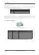
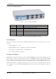
2 Introduction 2.2.2 VScom USB-2COM PRO Figure 3: VScom USB-2COM PRO Serial Ports Connectors Power FIFO size LED 2 2×DB9 male 2×Terminal block Bus powered 128 Bytes 384 Bytes Power 4×Data 2×Mode RS232, RS422, RS485 (6.1) RS422, RS485 (6.3) Transmit Receive On Top: Red LED On Top: Transmit Green, Receive Yellow per port On Top: 3-Color Table 4: Features of VScom USB-2COM PRO Dual Port 2.2.
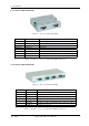
2 Introduction 2.2.4 VScom USB-8COM PRO Figure 5: VScom USB-8COM PRO Serial Ports Connectors Power FIFO size LED 8 8×DB9 male Self powered 128 Bytes 384 Bytes Power 16×Data 8×Mode RS232, RS422, RS485 (6.1) 110V - 240V AC, 48 - 67 Hz Transmit Receive On Front: Red LED In Block on Front: Transmit Green, Receive Yellow Near Port: 3-Color Table 6: Features of VScom USB-8COM PRO Octal Port 2.
3 The Drivers for Windows 3 The Drivers for Windows This chapter of the manual documents the drivers for Windows Operating Systems. The driver is the same for all USB-COM available, independent of the model. As one consequence there is only one driver for download, linked to from all the products. It does not matter which link you use. The USB-COM appear in Windows as several components, depending on the specific model. This can be seen in the Device Manager, while or after installation of the drivers.
3 The Drivers for Windows Figure 6: Starting Pre-Installation When the operation is finished, this box closes. No interaction is required. The result of this process is a Windows system which has the USB-COM added as know hardware. This installation process also added an entry in “Control Panel” (actually two entries), in the “Add or Remove Programs” applet. The drivers may be uninstalled by this entry. Figure 7: Uninstall Option Now connect your USB-COM to a USB port on your PC.
3 The Drivers for Windows of components. On both entries, click the Change/Remove button to remove the software from your system. Once both entries are done, the drivers no longer exist. This procedure not only removes all entries of USB-COM from the Device Manager, as the final step also the files are removed from the hard disk. As a result reconnecting a USB-COM causes Windows to start the “New Hardware” Wizard again. 3.
3 The Drivers for Windows Figure 9: Help the Wizard Usually Windows can not locate the best software automatically. Even if the driver is saved on a CD-ROM, the automatic option uses a long time to search. So instead select the “(Advanced)” option, and click on Next. Figure 10: Select appropriate driver Guide Windows to the directory where you saved the latest version or to the CD-ROM, and again click on Next.
3 The Drivers for Windows Figure 11: Driver installed Windows copies the drivers to the system directory, and loads them. After that the installation is done, so click on the Finish button. But this was the installation of the “USB FAST SERIAL ADAPTER”, not the serial ports themselves. These are also detected as new hardware, and the process repeats for these drivers. Follow the steps above a second time, and then you are done.
3 The Drivers for Windows Figure 12: USB Serial Port Properties Click on the button named “Advanced...” to see the special configuration options. They are available via panel 13.
3 The Drivers for Windows Figure 13: Advanced port options 3.3.1 Rename the Serial Port The option “COM Port Number” on top of the advanced settings allows to rename the port. You may select any free port number. It is Windows which refuses a change, if the new port name is already occupied. 3.3.2 Miscellaneous Options In the lower right corner of the Advance Options (figure 13) are some seldom changed options. 3.3.2.
3 The Drivers for Windows last part of the transmission does not trigger the 62 byte limit, this causes a delay in receiving the data. As the consequence the application can not operate on the data very early. Usually this is not a problem, but with certain serial protocols this can cause strange effects. So a reduction to 1 ms is appropriate then, faster reactions are not possible. This is caused by the protocol structure of USB, not by the serial port. 3.3.2.2 Serial Enumerator for different purposes.
3 The Drivers for Windows 3.3.2.7 Disable Modem Ctrl At Startup Usually on startup the modem control signals RTS and DTR follow the behavior of standard ports (i.e. Com1). Due to the longer timing compared to built-in serial ports a very short enable or disable pulse on the control signals may become a comparably long pulse on the USB serial port. Such a long pulse can cause external hardware to malfunction. By correct configuration of the serial port application software can avoid that problem.
4 Hardware Configuration 4 Hardware Configuration The hardware of VScom USB-COM PRO is not configured via Jumper blocks or DIP switches, as is mentioned above. Instead this is done by software. Each model has a single button named as “Config”. User press this button for at least 3 seconds, a blue LED inside the button will light. This shows the device is in configuration mode now.
4 Hardware Configuration Figure 14: UsbComCfg started If a device is not in Configuration mode, it is not detected. It is also not possible to find a device, when the first serial port is used by an application software. UsbComCfg repeats the search when the appropriate button is clicked. By clicking a device in the left pane, a port in the middle pane can be selected. The operation mode is then changed by the radio buttons and check boxes in the right pane.
4 Hardware Configuration Figure 15: UsbComCfg Multi-Port Selection You may select several ports of one device at the same time. This is done by the usual Windows method, i.e. clicking with Shift- or Ctrl-Key pressed. The selected configuration then applies to all selected ports, “Commit Changes” configures all of them at the same time.
4 Hardware Configuration Figure 16: UsbComCfg Multi-Device Selection Finally you may select multiple devices at the same time. The configuration then applies to all ports of all selected devices. Watching the LEDs on each device you can see how the configuration proceeds from device to device. When all USB-COM PRO are configured, they are still in Configuration mode, shown by the blue LED. Shortly press the “Config” button put the devices back to normal operation. The LED in the button will go dark. 4.
4 Hardware Configuration [2#1] USB-2COM PRO v1: please press to activate the menu Figure 17: Open Terminal Configuration Now press the “Config” button to enter the configuration mode. In your terminal screen a line similar to the above will appear. If you carefully watch the software, you may notice the line is written again and again. If your terminal application translates a to a sequence, it adds a Line Feed character to each line.
4 Hardware Configuration 4.2.2 Show Port Configurations (1) > 1 Port 1: RS232 Port 2: RS232 Figure 20: Show all port configurations The command ’1’ in the Main Menu lists the current configuration of all serial ports in the USBCOM PRO. This example is for a USB-2COM PRO with both ports in RS232 mode. The list is followed by the Main Menu again. 4.2.
4 Hardware Configuration ' > 1 ---> Port 1: RS232 -----------------------------------0 - Back -----------------------------------1 - RS485 by RTS, 4-wire 2 - RS485 by RTS, 2-wire no Echo 3 - RS485 by RTS, 2-wire with Echo 4 - RS485 auto, 4-wire 5 - RS485 auto, 2-wire no Echo 6 - RS485 auto, 2-wire with Echo 7 - RS422 8 - RS232 -----------------------------------9 - BIAS 10 - TxTerm 11 - RxTerm > & $ % Figure 22: Configure a serial port The options are selected by entering the number, followed by the En
4 Hardware Configuration ' ---------------------------------5 - Show configuration file 6 - Upload configuration file > 5 $ file construction (decimal values): 1. 2. 3. 4. port port port number mode (take a look at "Change port configurations") control bits (bit0: BIAS, bit1: TxTerm: bit2: RxTerm) (empty line) 99 terminates the file <-- file start --> 1 8 0 2 8 0 99 <-- file end --> & % Figure 23: Saving Configuration file The configuration is displayed on the terminal screen.
5 Technical Background on RS485 5 Technical Background on RS485 This chapter will provide a little bit of theory about RS422 and RS485 data transmission. It is necessary to have this basic knowledge, to avoid or find errors in data transmission. Failures in cabling are responsible for the vast majority of transmission problems. 5.1 Transmission Technique RS422 and RS485 use the same balanced transmission method. Signals are not transmitted by voltage on a single wire, as RS232 does.
5 Technical Background on RS485 5.3 Polarization In RS485 the sender must activate the transmitter before sending data, and deactivate it when all data is sent. At times when no devices send data all transmitters are inactive. As the result the data lines are floating, and the differential voltage is undefined. It may happen the next data is not correctly recognized, because the change from undefined to data signals is not detected. To avoid such problems the data lines should be polarized by resistors.
5 Technical Background on RS485 5.5 4-Wire Scheme RS422 requires dedicated wire pairs for transmit and receive. The transmit wires are used to send data to as many as 10 receivers, as stated in the specifications of RS422. Since the VScom products use RS485 line driver technology, up to 32 receivers are possible. While one pair is used to transmit, a second pair is available to receive data at the same time.
6 Connector Definitions 6 Connector Definitions All the VScom USB-COM devices provide the today standard DB9 male connector for the signals of the serial ports. Some models may offer a DB25 male connector for RS232, other may provide an additional Terminal block for RS422 and RS485 signals. The signal assignment for RS232 on DB9 male connectors is defined by the term “RS232” already. The same is for the DB25 male connector. Below is the signal definition for all connectors used by the USB-COMs. 6.
6 Connector Definitions 6.2 DB25 male RS 232 This connector is only available on the VScom USB-COM 25 model. The pins not mentioned are a no-connect. Pin 2 3 4 5 6 RS232 TxD RxD RTS CTS DSR Pin 7 8 20 22 RS232 GND DCD DTR RI Table 8: DB25 male RS232 Figure 27: DB25 male RS232 6.3 Terminal Block The Terminal Block connector is designed for connecting RS422 or RS485 signals. However it may be used for RS232, because the most important signals are available here.