Installation guide 7 (of 14)
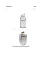
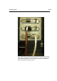
Fig. 3. Photo of the back side of a ROXY Potentiostat with serial communi-
cation cable connected to slot labeled “RS232 C” on the control board and
trigger cable connected to slot “A” of the cell 1 sensor board. The Power
inlet is located in the left, bottom corner.