ROXY EC system Installation guide Antec .... Proven Performance! 210.7011, Edition 1, 2010 Antec, Industrieweg 12, 2382 NV Zoeterwoude, The Netherlands T: +31 71 5813333, F: +31 71 5813334, E: info@myantec.com, W: www.myantec.
Copyright ©2010 Antec Leyden. All rights reserved. Contents of this publication may not be reproduced in any form or by any means (including electronic storage and retrieval or translation into a foreign language) without prior agreement and written consent from the copyright of the owner. The information contained in this document is subject to change without notice.
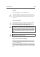
Installation guide 1 (of 14) Symbols The following pictogram is used in this installation guide: Caution, calls attention to a procedure, which, if not correctly executed, could result in damage to the equipment or personal injury. Do not proceed beyond a "CAUTION" sign until the indicated conditions are fully understood and met. General precautions Execute periodic leak checks on LC tubing and connections. Do not allow flammable and/or toxic solvents to accumulate. Do not close or block drains.
2 (of 14) ROXY EC installation guide, edition 1 Table of contents Symbols 1 General precautions 1 Spare parts and service availability 1 Table of contents 2 Requirements 4 Unpacking 6 Electrical connections (Mains, RS232 & trigger cable) 6 Liquid connections 9 Installation USB-COM driver & Dialogue software 10 Changing the COM port number (reconnecting the devices) 12 Dialogue for ROXY hands-on training 14
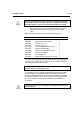
Installation guide 3 (of 14) Note that this document is only to guide you through the installation of an ROXY EC system and by no means is a replacement of the installation sections in the user manuals supplied with the system. □ Check all carton boxes, inform the transport company in case of damage. Store the transport boxes as they may be needed again. ROXY EC system is delivered as the set of the following parts: Part no. Description Qty 180.0161A 188.0035 188.0300 188.0302 250.0123C 210.0050 210.
4 (of 14) ROXY EC installation guide, edition 1 Requirements The size requirement for an ROXY EC system are as follows: Description ROXY Potentiostat Syringe pump Dimensions 44 (D) x 22 (W) x 44 (H) cm 11.4 (D) x 23 (W) x 14 (H) cm Weight 14 kg 2.2 kg □ Prior to installation, it is advised to make enough space available on the lab bench/table.
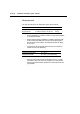
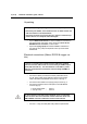
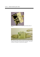
Installation guide 5 (of 14) Fig. 1. Front view of the possible ROXY EC system configuration. Fig. 2. Photograph of the ROXY EC system configuration.
6 (of 14) ROXY EC installation guide, edition 1 Unpacking Advice (for IQ) during unpacking of the individual system parts: ● Check the part number, serial number on the s/n label of each unit and write it down in the IQ document. ● Check the contents of accessory kits etc. using the checklist supplied to assure it is complete and undamaged. □ □ Unpack ROXY Potentiostat and follow installation instructions in user manual and next section of this document.
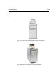
Installation guide 7 (of 14) Fig. 3. Photo of the back side of a ROXY Potentiostat with serial communication cable connected to slot labeled “RS232 C” on the control board and trigger cable connected to slot “A” of the cell 1 sensor board. The Power inlet is located in the left, bottom corner.
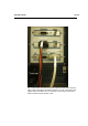
8 (of 14) ROXY EC installation guide, edition 1 Fig. 4. Photo of the back side of a syringe pump with serial cable connected. Fig. 5. Photo of the USB – RS232 converter with serial cables from potentiostat and syringe pump connected to Serial 1 and Serial 2, respectively. Converter is connected to computer using an USB port.
Installation guide 9 (of 14) Liquid connections □ Follow the instructions in the supplied LC connection kit installation guide for installation of all liquid connections. Connect the tubing as it is shown in the drawing delivered with the connection kit (180.7161A). Fig. 6. As an example the front side of the schematic installation drawing of all LC connections of the ROXY EC system is shown. Every kit is delivered with a similar schematic installation drawing.
10 (of 14) ROXY EC installation guide, edition 1 Installation USB-COM driver & Dialogue software □ Verify if the PC specifications and operating system are in compliance with the PC requirements document (p/n 210.7050). Change PC energy saving settings, virus scanner settings if necessary. If possible export the PC system info to text file and save a copy on a USB memory stick for future reference.
Installation guide 11 (of 14) □ After installing the Dialogue: Switch on devices Run Dialogue software from Start menu (in 'Antec software') AFTER running Dialogue (which installs dongle drivers), insert the license dongle and restart the software ROXY Potentiostat should be automatically detected (If no detector is present, Dialogue software will continue running in 'demo' mode.) □ Go to Options Settings RS232 to connect the syringe pump (Fig.7).
12 (of 14) ROXY EC installation guide, edition 1 Changing the COM port number (reconnecting the devices) To change the COM port number: 1. Go to Control Panel. 2. Open the Device Manager. 3. Go to Ports (COM & LPT). Right Click on the COM to which Potentiostat is connected and choose Properties. Fig. 8. Control panel COM port settings after connecting converter (COM numbers automatically assigned by Windows. 4. Go to Port Settings Advanced and choose the desired COM number (7 for ROXY Potentiostat). 5.
Installation guide 13 (of 14) Fig. 9. Control panel COM port settings after manual change of COM port numbering. 6. Restart the PC to assure that all COM port changes are activated. 7. Restart the Dialogue and check the COM numbers in the OptionsSettings RS232 8. The syringe pump COM number must be entered by user manually (enter: 8). Once, the devices are connected click “fixed” to avoid automatic scanning all ports the next time Dialogue is opened.
14 (of 14) ROXY EC installation guide, edition 1 Dialogue for ROXY hands-on training Information how to operate the ROXY EC system is provided in the document Dialogue for ROXY – User Guide (p/n 210.7017). In the directory ‘TRAINING’ on the Antec Software CD (p/n 250.9010) a Dialogue for ROXY hands-on training is available dedicated to the ROXY EC system. The training material consist of the following files: 210_7018_xx.pdf 210_7018_xx.