
User Manual

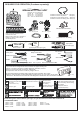
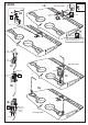
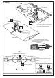


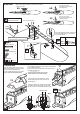


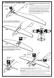
Table Of Contents

! Engine thrust on balk head
is already adjust at factory
SIDE-VIEW
Reposition the engine mount beams on to the fire-wall
and secure them with four 4x25mm screw (8A)
...................4
....................4
4x25mm screw - washer
Blind-nut - wooden washer
Insert the blind-nut with the wooden washer onto each
of the four holes make above.
110-115mm
FUSELAGE
Position the engine to the engine mounts so the distance
from the prop hub to the fire-wall is 110-115mm.
Mark the engine mounting plate where the four holes
are to be drilled (8B)
8A
3mm
Remove the engine and drill a 3mm holes through the
beam at each of the four marks made above (8C)
Reposition the engine on the engine mount beams, aligning
it with the holes. Secure the engine to the engine mount
using four 3x25mm screws (8D)
Note: Apply Silicon sealer to each
of the 3x25mm screw.
.......4
3x25mm screw
Washer
.......4
Cut the wood along the line as shown
(9A) in case of 2T engine using
Attach the engine mount beams onto the fire-wall so the distance between of
two engine mount beams is “A”,and B=B’ as show.
Secure the engine mount beams onto the fire-wall with litter CA glue (9B)
! Align the mark on both engine mount
beams with the mark on the fuselage
B
B’
A
B=B’
FRONT-VIEW
A
B
B’
Using a pencil or felt tipped pen, mark the fire wall where the four holes are to
be drilled(9B)
9A
8-ENGINE
8B
8C
8D
9-ENGINE
9B