
User Manual
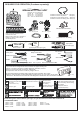
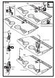
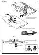


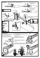


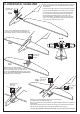
Table Of Contents

2 mm
Turn the Hex wrench
and adjust the flap pushrod
(closed position)
Slide the flap push-rod to the hole of the connector
on the servo arm.
Slide the flap push-rod to the hole
of the connector on the servo arm.
6A
The hole for flap adjust
............4
2mm
Connector
Plastic control horn
............2
2x20mm screw
..............4
Aileron push rod
......2
..2
The vertical portion of the control horn
must be positioned so it is centered
over the hinge line
3/8 in. (9.5mm)
Turn the Hex wrench
and adjust the flap pushrod
(opening position)
L/R
Assemble left and right
sides the same way.
FRONT-VIEW
6mm
Turn the black plastic screw on both
side of the fuselage to pull the canopy
hatch out of the fuselage (7A)
Cut the wood along the line as shown
(7B) in case of 4T engine using
7A
B
B’
! Align the mark on both engine mount
beams with the mark on the fuselage
Using a pencil or felt tipped pen, mark
the fire wall where the four holes are to
be drilled(7C)
Carefully remove the engine mount beams
and drill a 6mm hole through the fire-wall
at each of the four marks made above (7D)
Attach the engine mount beams onto the fire-wall
so the distance between of two engine mount beams
is “A”,and B=B’ as show.
Secure the engine mount beams onto the fire-wall
with litter CA glue (7C)
A
A
B
B’
A
B=B’
6-WING
6A
6B
6C
2mm
6D
7-ENGINE
7B
7C
7D