
User's Manual

be varied to reduce or eliminate unwanted reflections. Please refer to pages 24 to 28 for further mounting
information.
Power Supply Connection
400A series clocks may be supplied for 230v ac, 110/120v ac, 12v dc, 24v dc or 48v dc. The clock must be
connected to the appropriate supply after first verifying the correct voltage by reference to the supply voltage
label fixed to or printed on the rear panel of the clock.
A connection to the earth line must be made to ensure safe operation and ensure compliance
with EMC regulations.
To ensure conformance with EN60950:
(A) For installations where the 400A clock is to be permanently connected into the mains power
circuit, a readily accessible disconnect device should be incorporated in the fixed wiring.
(B) For installations where the 400A clock is to be plugged into the mains power circuit, a
socketed outlet should be installed near the equipment and should be easily accessible.
All installation work should be performed in accordance with the Sixteenth Edition of the IEE
Wiring Regulations.
An internal automatically re-charging battery will, when fully charged, maintain the internal time count for a
period normally in excess of 60 hours if the mains supply is interrupted.
The power supply is fitted with an internal 100mA fuse (450A, 490A.05 etc = 160mA fuse). In case of fault
the fuse should only be replaced by a suitably qualified engineer after disconnection from the mains
power supply and correction of the fault condition.
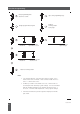
External Signal Connection
A six way terminal block is located on the rear panel of the clock to enable the connection of external signals.
Details of the connections for various signal configurations are shown on page 28.
The mains power supply must be disconnected when making connections to external signals.
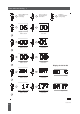
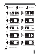
Manual Time Synchronisation
The 400A clock or calendar clock should be set to time of day, when used in stand-alone mode, prior to the
connection of a synchronising impulse signal or in the absence of the required synchronising code or radio
signal, by means of the three time setting switches located on the rear of the clock. The locations of these
switches are illustrated on pages 24 and 28 and the setting sequence is detailed on pages 4 and 5.
401A, 420A and 490A series clocks which normally display time only may also be set to date in order to
enable automatic pre-programmed seasonal time-changes and to provide date information for serial ascii data
outputs if an optional internal serial interface module is fitted.
Optional Internal Interfaces
A range of optional internal interfaces allow connection of the clock to a variety of signals and external
equipment. The appropriate interfaces are normally factory fitted in accordance with order specification.
If it is necessary to fit a new internal interface in order to change the specification of the clock the work must
be carried out by a suitably qualified engineer in accordance with the instructions on page 20.
Guarantee
The 400A series clocks are fully guaranteed, on a return to works basis, against failure due to faulty parts or
workmanship for one year from date of purchase. In the event of failure, either within or outside the warranty
period, please pack the unit with care and return it to our factory for examination and repair.
3
Introduction - 3
Issue 2.2