
User's Manual

Temperature Display
Two temperature display modes are available. The temperature may be displayed continuously or alternately
exchanged with the hours and minutes time display. When the alternate time/temperature display mode is
selected the period between display changes may be adjusted by the user.
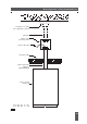
An external type 406 Temperature Sensor module is required to allow temperatures in the range -17°Cto
+50°C to be displayed. The 406 module is normally supplied with a three core, 5m connecting cable which
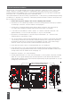
may be user extended up to a maximum of 100m. The connection of the module to the 400A series clock is
illustrated on page 28 of this manual.
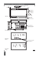
The 406 module is housed in a two part, clip together, ventilated case measuring 70mm x 70mm x 25mm
deep. The module may be mounted on a suitable vertical surface, either by the use of two strips of double
sided tape or by mechanical fixing via two screws through the marked positions in the detachable base plate
of the unit. The module must be mounted in a position where it is not subject to direct rain or other water
spray.
Please refer to pages 4 - 9 of this manual for programming information.
Important note: The clock should be programmed to the required temperature display function with the
temperature sensor disconnected. The temperature sensor must be connected to the clock after the required
display mode has been programmed.
To program a 400A series clock to display temperature information program function 7 should be set to
selection `C’ to display alternating time and temperature or selection ‘°’ to display the temperature only.
The temperature sensor is factory calibrated to
+
/
-
1°C. However any temperature display system is subject to
errors caused by installation location related environmental conditions. The correct temperature should be
established by reference to an accurate shielded thermometer. Program function 8 allows the displayed
temperature to be corrected to compensate for errors, when program function 8 is selected the display flashes
on/off showing the adjusted temperature. The displayed value may be adjusted, up or down by up to 5
degrees, to the required corrected value by use of the `B’ setting switch. The correction factor is permanently
stored in non-volatile memory.
Program function 13 allows the `hold time’ between display changes to be set in the range 1 to 15 seconds.
Note that the alternating cycle is always returned to show time information at the start of each new minute.
Local Master Clock Mode
The local master clock mode enables any 400A series clock, when fitted with an internal 404.M interface
module, to control up to ten 400A clocks operating as slaves with a maximum cable length of 200m.
A 400A clock will only operate as a `local master’ clock if, in addition to having a 404.M module installed, it
is maintaining its timekeeping from the internal high stability crystal (stand-alone synchronisation mode) or it
is synchronised to MSF or DCF radio time code via a 484 series receiver.
Any 400A clock will operate as a `local slave’ as the interface circuit is present as standard.
The master clock should be programmed, by reference to pages 4 - 9 of this manual, as follows:
• Program function 3 - Synchronisation mode - selection 1, 9, 10, 11 or 12 as appropriate
• Program function 7 - External Controller mode - selection 0
• Program function 9 - Serial Output mode - selection 0
Each slave clock should be programmed as follows:
• Program 3 - Synchronisation mode - selection 17
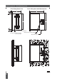
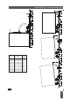
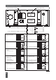
The slave clocks should be connected in parallel to the master clock, by reference to the connection diagrams
shown on page 28 of this manual, using a single twisted pair cable.
The interconnecting cable may be unscreened in the majority of installations but should be screened in the
presence of high levels (1Vm) of radio frequency emissions or when the interconnecting cable runs are
adjacent to machinery or equipment likely to produce significant levels of electrical noise.
If screened cable is used the screen should be grounded at the 400A local master clock end only.
22
Special Operating Modes
Issue 2.2