
User's Manual
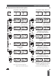

Internal Interface Module required
Program 3 Selection Option
402A Stopwatch Controller
402A with switch closure at 00:00.0
496A Stopwatch Controller
Alternate Time & Temperature Display
Serial Ascii Output every second
Serial Ascii Output on RS232/485 trigger
Serial Ascii Output on Switch Closure
400A Master Output to Control up to
10 slave clocks
Synchronisation Mode
Stand-alone None 1 4 44444 44
Impulse None 2 -7 488 48888
W482 Time Code None 8 488 48888
MSF & DCF Radio None 9 - 12 44844444
Time Code
IRIG-B & afnor 404.I 13 -14 88888 888
Nf S 87-500 Code
EBU/SMPTE 404.E 15-16 88888888
Time Code
400A Local None 17 48 8 4 8 8 8 8
Slave Mode
RS232 404.2 18-20 88888 888
Serial Ascii
RS485 404.4 18-20 88888 888
Serial Ascii
H310 None 21 48 84888 8
Time Code
Mobaline None 22 48848888
Time Code
GPS code from None 23 488 48 88 8
488GPS System
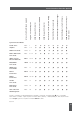
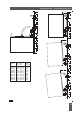
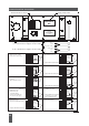
System configurations indicated by 4 are available. Configurations indicated by
8 are not available.
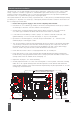
Serial RS232 or RS485 outputs require an internal 404.2 (RS232) or 484.4(RS485) module. 400A Master
Clock output operation requires an internal 404.M module.
21
Internal Interface Function Options
Issue 2.2