
User's Manual

The 400A series of clocks and calendar clocks may be programmed to synchronise to and to output a wide
variety of signals. In a number of applications, as detailed throughout this manual, an optional internal
interface module must be added in order to convert the external signals into the logic levels required by the
400A series clock or to generate the appropriate output signal levels.
The required interface module will normally, if specified at time of order, be factory installed during the testing
procedure prior to dispatch. If it is necessary to subsequently install an interface module in a 400A series clock
the following steps must be taken.
• Ensure that any power supply to the clock is completely disconnected.
• Place the clock on a conductive, grounded, work-surface ensuring that the case body is protected to
avoid damage to the finish of the case and the front display filter.
• Unscrew the cross-head self-tapping screws which hold the rear panel to the clock case body.
A ‘Pozidrive’ type screwdriver should be used and the screws saved for re-assembly.
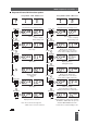
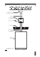
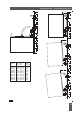
• Locate and remove the battery connection jumper - J4 - which is located above the end of the
right-hand battery. To avoid loss retain the jumper on one pin of the J4 header.
• By reference to the drawing below, locate the ten pin vertical header - J5 -andremovethe
standard jumper connecting pins 2 and 3.
• The optional interface module must be installed with the ten way female socket mating with header
- J5. The body of the female socket must be towards the square processor chip and on the side of
the interface module away from the transformer and batteries. The side of the module carrying
surface mounted components must be towards the batteries and transformer.
• Ensure that the module socket is correctly aligned with the - J5 - header pins.
• Ensure that the flat, 20 way, interconnecting cable assembly between the display printed circuit
board and the power/logic printed circuit board is correctly in place with the cable mounted socket
securely seated on the shrouded board mounted plug - J6.
• Replace the J4 jumper to re-connect the battery.
• Carefully replace the back cover of the clock ensuring that no strain is placed on the interconnecting
cables. All of the original retaining screws must be replaced to ensure electrical and mechanical
safety and EMC screening. If any screws have been misplaced they may be replaced with No. 4 x 3/8”
self tapping countersunk screws.
P95/01A
J5
J6
J4
J5 - Interface module connector
J4 - Remove jumper to
J4
Typical module installed
Jumper required for standard operation
- remove to fit interface option module
disconnect battery
program memory
processor
20
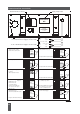
Internal Interface Installation
Issue 2.2