
User's Manual

TimeLord Master Clocks
Operating and Installation Instructions
Issue 2.0
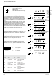
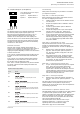
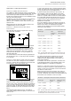
V-02 .IMP Dual Impulse Output
6 way terminal block
Impulse 1 Impulse Channel 1
Impulse 2 Impulse Channel 2
12-1
12 - Impulse Output (V-02 Option)
Operation
The TimeLord master clock is optionally available with dual channel
24V alternate polarity impulse outputs (Option V-02).
Each output may be programmed by the user for one of a
number of different combinations of pulse length and
repetition rate to drive impulse slave clocks requiring one
second, half minute or one minute alternate polarity impulses.
The fully protected output drive circuits detect power failure
and short circuit line fault conditions which are automatically
corrected for on fault removal.
Automatic Correction
Automatic time correction following power failures, the
removal of fault conditions and after seasonal time changes is
carried out by increasing the pulse repetition rate or by
stopping the impulses depending on which action will result in
a shorter correction time.
In the 1 second - standard mode the system will take one hour
to correct for each hour that the slave clocks are behind the
master.
In the 1 second - slow correction mode the system will take
approximately one and a half hours to correct for each hour
that the slave clocks are behind the master.
The 1 second - seconds synchronisation only mode is intended
for use with 4 wire slave clocks requiring both minute and
second impulses.
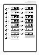
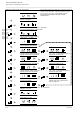
elbaTepyTtuptuOeslupmI
edoC edoM
nontuptuooNtuptuooN
tuptuooN
tuptuooNtuptuooN
AS1dradnats-dnoces1dradnats-dnoces1
dradnats-dnoces1
dradnats-dnoces1dradnats-dnoces1
etunimrepseslup021,eslupmignol.ces4.0
.deepspu-hctac
bS1noitcerrocwols-dnoces1noitcerrocwols-dnoces1
noitcerrocwols-dnoces1
noitcerrocwols-dnoces1noitcerrocwols-dnoces1
-hctacetunimrepseslup58,eslupmignol.ces4.0
.deepspu
cS1ylnosdnoces-dnoces1ylnosdnoces-dnoces1
ylnosdnoces-dnoces1
ylnosdnoces-dnoces1ylnosdnoces-dnoces1
tnemevomsdnocesehtrof-eslupmignol.ces4.0
setunimdnasdnocesetarapeshtiwskcolcevalsfo
.smsinahcem
S03etunim2/1etunim2/1
etunim2/1
etunim2/1etunim2/1
-hctacetunimrepseslup03,eslupmignol.ces5.0
.deepspu
An1dradnats-etunim1dradnats-etunim1
dradnats-etunim1
dradnats-etunim1dradnats-etunim1
-hctacetunimrepseslup03,eslupmignol.ces0.1
.deepspu
Bn1noitcerrocwols-etunim1noitcerrocwols-etunim1
noitcerrocwols-etunim1
noitcerrocwols-etunim1noitcerrocwols-etunim1
-hctacetunimrepseslup6,eslupmignol.ces0.3
.deepspu
Commissioning
Please perform the following four procedures to commission
your impulse clock system.
Setup Part A - Initial Setup Procedure
Before commencing this procedure, please ensure that all of
the clocks are displaying the same time.
1) Install the TimeLord master clock as detailed in section
3 of this manual.
2) Program the required location as detailed in section 4
of this manual.
3) Connect any synchronisation option as detailed in
section 5 of this manual.
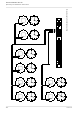
4) Connect the analogue clocks to your chosen impulse
channel as shown on page 12-4. Please refer to
appendix A for recommended cable specifications.
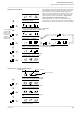
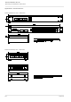
5) For your chosen impulse channel, program the required
‘Impulse output type’. This is part of the impulse
channel setup procedure shown graphically on page
12-2. The ‘Impulse Output Type Table’ below details
the options available.
Setup Part B - Synchronisation of clocks
This procedure ensures that all clocks on your chosen impulse
channel are synchronised together. Before starting this
procedure you should ensure that all clocks are displaying the
same time.
6) Referring to the ‘starting the impulses’ procedure on
page 12-3, select the ‘pulse’ option and press the ‘^’
key. This action transmits a single pulse to all of the
connected clocks.
7) Now examine the slave clocks. Reverse the impulse
connections to all slave clocks that appear to have
‘missed’ a pulse and manually advance these clocks by
two impulses. All clocks connected to this channel
should now be in synchronisation.
Setup Part C - Programming the Impulse time
8) For your chosen impulse channel, program the ‘Impulse
Time’. This is part of the impulse channel setup
procedure shown graphically on page 12-2. The
‘Impulse Time’ is the time that the analogue clocks are
currently displaying. Please note that you must ensure
that all of the analogue clocks on your chosen impulse
channel are showing the same time.
Setup Part D - Starting the Impulses
9) Referring to the ‘starting the impulses’ procedure on
page 12-3, select the ‘run’ option and press the ‘^’ key
to exit.
The channel will now be running and the master clock will
calculate whether it will be quicker to output catch-up
impulses or wait for the current time to reach the impulse time
(as previously programmed).
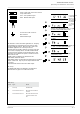
Visual Indication of Operation and Error status
The TimeLord.IMP master clock provides full time visual indication
of impulse channel operation and alarm status. When an
impulse is transmitted, the relevant channel LED will illuminate
below the time display on the front panel. If an overload or
short circuit line fault occurs, the impulse alarm LED will flash
along with the relevant channel LED.
The current impulse time of channels 1 and 2 may be
examined by pressing the ‘+’ key three or four times
respectively when on the standard time display.
Please refer to page 12-3 for further details.