
User's Manual

Issue 2.0
TimeLord Master Clocks
Operating and Installation Instructions
5-3
MSF and DCF synchronisation
MSF and DCF are the two most widely used radio time code
signals. The DCF signal is derived from the atomic clocks at the
Physics Institute of Brunswick and transmitted at a frequency
of 77.5KHz from Manflingen, near Frankfurt in Germany. The
MSF signal is referenced to the Caesium Beam Oscillators at
the National Physical Laboratory and transmitted on a
frequency of 60KHz from Rugby in the United Kingdom.
Under normal circumstances the DCF signal provides reliable
operation at distances of up to 1500km, MSF signals are
normally usable up to 1000km from the transmitter. Greater
operating ranges are possible at night.
When synchronised to MSF or DCF using a V-484 radio receiver
the TimeLord Master Clock output signals are maintained
within 30mS of UTC.
Advantages of MSF and DCF time synchronisation:
• Lower purchase cost than GPS
• Can sometimes be installed internally.
Disadvantages of MSF and DCF time synchronisation:
• Can be difficult to find good location for signal
reception.
• Suffers greatly from EM interference - Avoid locating
near computers, electronic equipment, fluorescent
lighting, lift equipment, metal girders, reinforced
concrete walls and all other sources of electrical noise.
• MSF is off-air for a maintenance period of two weeks
during the summer, and the first Tuesday of every
January, April, July and October. MSF status can be
checked by telephoning 020 8943 6493.
Installation
The V-484 series time code receiver should be mounted:
• At least 2.5 metres from the TimeLord Master Clock.
• At greatest practical distance from:
Other electronic equipment including computers,
fluorescent lights and signs, metal girders, reinforced
concrete walls and any other sources of electrical noise.
• On the side of the building nearest Rugby (MSF) or
Frankfurt (DCF).
• Preferably on the outside of the building (V-484.02 and
V-484.03 only) as high as possible. The case is
weatherproof to IP65 (484.02 and 484.03 only) but it is
preferable to provide some protection from direct rain.
• With the cable entry on the lower face of the case.
(V-484.02 and V-484.03 only)
The antenna is supplied with 5 metres of two core cable, if a
longer cable distance is required Appendix A should be consulted
for suitable cable specifications. The maximum distance
between the V-484 radio receiver and the TimeLord Master
Clock is 200m.
If a screened cable is used, the cable screen should be connected
to the EMC grounding terminal on the 10 way terminal block,
located on the rear of the TimeLord.
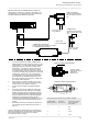
Alignment
The V-484.02 (MSF) and V-484.03 (DCF) radio receivers have dual
ferrite antennas, which normally permit location regardless of
orientation to the transmitter. The receiver is mounted by means
of four fixing holes in the rear surface which are accessed after
removing the front cover. The four mounting holes are located
outside of the central sealed compartment.
The V-484.06 (MSF) and V-484.07 (DCF) receivers have a single
antenna element and are supplied with an adjustable
mounting bracket so that the installer can ensure that the
orientation of the longest face of the receiver is at 90
o
to the
direction of the transmitter.
The front cover of the V-484.02 and V-484.03 receivers may be
removed to enable the indicator LED to be viewed. The indicator
LED on the V-484.06 and V-484.07 receiver is located on the front
face of the unit.
The alignment of the receiver is correct when the LED flashes
once per second. The Code LED located on the front of the
TimeLord will flash at the same time as the LED in the V-484.
Signal reception
In good conditions the TimeLord master clock will take three
minutes to synchronise with the transmitted time code from
either DCF or MSF. When the TimeLord is ‘locked’ to the
transmitted signal, the locked LED, located after the seconds
display, is illuminated continuously. During periods of signal
failure or signal corruption the clock will maintain timekeeping
using its internal crystal oscillator.
1 PPS / Serial ASCII Synchronisation
Special order versions of the TimeLord Master Clock are available
to facilitate synchronisation with an RS232 / RS485 level serial
ASCII data string or timebase generation from an RS232 /
RS485 level 1 Pulse Per Second source. The Serial variant will
synchronise to Serial format 1 (as shown on page 7.1)
transmitted at 9600 baud, 8 data bits, no parity, 1 stop bit at a
1 second repetition rate.
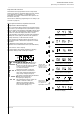
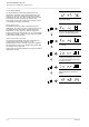
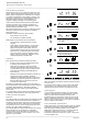
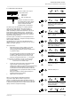
Normal time display
Function ‘Time Setting Mode’. Press ‘+’
twice to move to synchronisation mode.
Function ‘Synchronisation Mode’. Press
‘^’ to select.
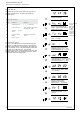
Synchronisation mode selected with
current mode flashing. Use ‘+’ and ‘-’
to select required setting.
Press ‘^’ to save synchronisation mode
and return to normal time display.
Normal time display.