
User's Manual

Issue 2.0
TimeLord Master Clocks
Operating and Installation Instructions
GPS Synchronisation
The V-488C and V-488B GPS receiver systems are designed to be
automatically synchronised to time signals transmitted from
the Global Positioning System (GPS) navigation network. The
GPS constellation consists of 28 operational satellites,
operating in 12 hour orbits at an altitude of 20,200km.
Both the V-488C and the V-488B GPS receiver have been designed
for simple installation and operation by the end-user, requiring
only a 4 wire interconnection to the TimeLord Master Clock.
When synchronised to a V-488C or 488B GPS receiver system the
TimeLord-Net Master Clock output signals are maintained within
50uS of UTC (100uS of UTC on TimeLord-Lite versions).
The reception gain pattern of both GPS systems is designed
for full, upper hemispherical coverage with the gain
diminishing at low elevations. This cross-section is consistent
through 360 degrees and so the 3 dimensional gain pattern is
a symmetrical spheroid surface.
Advantages of GPS time synchronisation:
• Very accurate synchronisation
• Can be used anywhere in the world
• Not subject to EM interference
Disadvantages of GPS time synchronisation:
• Antenna needs to be mounted externally with a clear
view of 75% of the sky.
The V-488C GPS Synchronisation System
The V-488C GPS synchronisation system is housed in a single
IP66 rated case containing an advanced combined Sony active
antenna and 12 channel parallel GPS receiver module and a
microprocessor based communications interface. The system
is supplied complete with a post mounting clamp to enable
the unit to be fixed to a suitable horizontal or vertical post of
up to 2cm diameter. The antenna should be mounted on the
roof of a building or under a suitable skylight.
The V-488B GPS Synchronisation System
The V-488B GPS receiver system comprises a post mounting
active antenna and a separate receiver/decoder unit. The
antenna module transmits the received GPS signals and
receives power (5Vdc @ 25mA) from the GPS receiver/decoder
module via a single 5 metre long RG58 coaxial cable. A post
mounting clamp is supplied to enable the antenna to be fixed to
a suitable horizontal or vertical post of up to 2cm diameter. The
antenna may be mounted on the roof of a building or under a
suitable skylight.
The GPS receiver/decoder unit contains a Motorola 8 Channel
parallel receiver and a microprocessor based communications
interface. The receiver/decoder module is housed in a robust
aluminium case fitted with mounting points for wall mounting
and protected to IP65. The module should be mounted in a
protected location within 5 metres of the antenna.
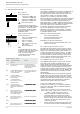
V-488C and V-488B System Installation
To ensure ease of operation and to remove the possibility of
operator error, both the V-488C and V-488B GPS systems are
designed to self initialise.
Ensure that the TimeLord is disconnected from the
mains power supply when making connections to the
V-488C / V-488B GPS receiver systems.
1 Install the V-488C unit or V-488B antenna module
horizontally using the post mounting kit provided.
Ensure that the unit has a clear view of at least 75% of
the sky. If the sky view is reduced the interval between
‘switch-on’ and system time synchronisation will be
considerably increased.
2 Connect the antenna module to the GPS receiver using
the special 5m cable provided (V-488B systems only).
5-1
5 - Synchronisation Setup
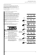
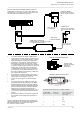
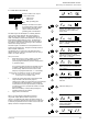
GPS connection
10 way terminal block
- -ve Power for V-488B/C GPS
+ +ve Power for V-488B/C GPS
A Signal A from V-488B/C GPS
B Signal B from V-488B/C GPS
EMC grounding point
Note:
A Screened cable should be used to
connect the V-488C / V-488B GPS receiver
to the TimeLord . The screen should
be connected to the EMC grounding
point on the TimeLord and on the
V-488B GPS receiver.
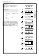
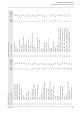
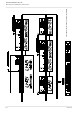
puteSnoitasinorhcnyS
edoC noitasinorhcnyS
ecruos
setoN
enoNgnisunoitarepoenoladnatS
OXCTlanretni
,ecnereferlanretxeoN
1.0nahtrettebycarucca
Cº52-02(Cº54-0.yad/ces
.TimeLord-Liteno
SPGrevieceRSPGB88488C/4-V
noitasinorhcnyS-metsyS
.setilletasSPGmorf
.ecruosemitetaruccayreV
nierehwynadesuebnaC
.dlroweht
FCD V-484 DCF Recever -
ehtmorfnoitasinorhcnyS
.langisemitFCD
FSM V-484 MSF Receiver -
ehtmorfnoitasinorhcnyS
.langisemitFSM
SPP1-dnoceSrePesluP1
1morfdetarenegesabemiT
laires584SR/232SRtaSPP
.slevel
noitpOredrOlaicepS**noitpOredrOlaicepS**
noitpOredrOlaicepS**
noitpOredrOlaicepS**noitpOredrOlaicepS**
reS-gnirtSataDIICSAlaireS
namorfnoitasinorhcnyS
IICSAlaires584SR/232SR
.margeletetad&emit
noitpOredrOlaicepS**noitpOredrOlaicepS**
noitpOredrOlaicepS**
noitpOredrOlaicepS**noitpOredrOlaicepS**
PTN-locotorPemiTkrowteN
namorfnoitasinorhcnyS
ecruoSemiTPTN
DxidneppaotreferesaelP
0084- noitpOredrOlaicepS**noitpOredrOlaicepS**
noitpOredrOlaicepS**
noitpOredrOlaicepS**noitpOredrOlaicepS**
GIRInamorfnoitasinorhcnyS
.ecruosedocemiTB-GIRI
noitpOredrOlaicepS**noitpOredrOlaicepS**
noitpOredrOlaicepS**
noitpOredrOlaicepS**noitpOredrOlaicepS**
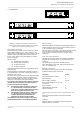
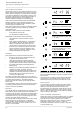
MSF and DCF connection
10 way terminal block
- Green or uncovered wire from
V-484 radio receiver.
+ Link to ‘A’ connector.
A Link to ‘+’ connector.
B Red or clear wire from V-484
radio receiver.
EMC grounding point
Note:
A Screened cable should be used to
connect the V-484 radio receiver to the
TimeLord in areas of high electrical
noise. The screen should be
connected to the EMC grounding
point on TimeLord only.
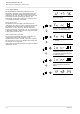
uncovered
clear
Green or
Wire link
AB
Red or
-+
GPS Receiver
w482
Relay
A B no nc C
nc
Relay
+
GPS Receiver
- A B
w482
ABno C