6.4L DOD GE/C Cha HRY SLER lleng Sup Inst erchar g alla tion er Sys tem Inst 201 1-20 r ucti 12 M ode ons l Ye ars* *Lega l in C alifor nia fo r racin g veh icles which may neve r be u sed u pon a er highw ay. ® ENGINEERING, INC. 1650 PACIFIC AVENUE • CHANNEL ISLANDS, CA 93033-9901 • (805) 247-0226 FAX (805) 247-0669 • www.vortechsuperchargers.com i P/N: 4CL020-020 v1.0, 12/02/2014 ©2014 Vortech Engineering, Inc All Rights Reserved, Intl. Copr.
FOREWORD T his manual provides information on the installation, maintenance and service of the Vortech supercharger kit expressly designed for this vehicle. All information, illustrations and specifications contained herein are based on the latest product information available at the time of this publication. Changes to the manual may be made at any time without notice.
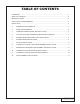
Table Of Contents FOREWORD...................................................................................................................................... ii TABLE OF CONTENTS...................................................................................................................... iii IMPORTANT NOTES......................................................................................................................... iv TOOL & SUPPLY REQUIREMENTS..........................................
OFF-HIGHWAY USE When driving vehicle on non-public roads (off-road applications such as racing/high RPM) Vortech strongly recommends reducing the factory spark plug gap down to .032”. COPYRIGHT NOTICE This product is protected by state common law, copyright and/or patent. All legal rights therein are reserved. The design, layout, dimensions, geometry and engineering features shown in this product are the exclusive property of Vortech Engineering, INC..
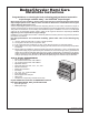
Dodge/Chrysler Hemi Cars Installation Instructions Congratulations on selecting the best performing and best backed automotive supercharger available today... the VORTECH® Supercharger! Before beginning this installation, please read through this entire instruction booklet and the Street Supercharger System Owner’s Manual which includes the Automotive Limited Warranties Program and the Warranty Registration form. Vortech supercharger systems are performance improving devices.
2011-2012 6.4L Automatic Challenger Tuner Kit Part No. 4CL218-164L ® PARTS LIST ENGINEERING, INC. IMPORTANT: Before beginning installation, verify that all parts are included in the kit. Report any shortages or damaged parts immediately. PART NO. DESCRIPTION QTY 008110 small silver die cut decal 2 008130 LICENSE PLATE FRAME, VORTECH 1 008341 VORTECH CHARGE COOLER DECAL 1 008447 1 YR S/C STRT INFO PKG ASY VOR 1 009035 S/C LUBE, BOTTLED, VORT 3-PACK 1 2A046-106 BELT PREMIUM 104.
2011-2012 6.4L Automatic Challenger Tuner Kit (cont’d) Part No. 4CL218-164L ® PARTS LIST ENGINEERING, INC. IMPORTANT: Before beginning installation, verify that all parts are included in the kit. Report any shortages or damaged parts immediately. PART NO. DESCRIPTION QTY 008110 small silver die cut decal 2 008130 LICENSE PLATE FRAME, VORTECH 1 008341 VORTECH CHARGE COOLER DECAL 1 008447 1 YR S/C STRT INFO PKG ASY VOR 1 009035 S/C LUBE, BOTTLED, VORT 3-PACK 1 2A046-106 BELT PREMIUM 104.
2011-2012 6.4L Manual Challenger Tuner Kit Part No. 4CL218-174L ® PARTS LIST ENGINEERING, INC. IMPORTANT: Before beginning installation, verify that all parts are included in the kit. Report any shortages or damaged parts immediately. PART NO. DESCRIPTION QTY 008110 small silver die cut decal 2 008130 LICENSE PLATE FRAME, VORTECH 1 008341 VORTECH CHARGE COOLER DECAL 1 008447 1 YR S/C STRT INFO PKG ASY VOR 1 009035 S/C LUBE, BOTTLED, VORT 3-PACK 1 2A046-106 BELT PREMIUM 104.
2011-2012 6.4L Manual Challenger Tuner Kit (cont’d) Part No. 4CL218-174L ® PARTS LIST ENGINEERING, INC. IMPORTANT: Before beginning installation, verify that all parts are included in the kit. Report any shortages or damaged parts immediately. PART NO. DESCRIPTION QTY 008110 small silver die cut decal 2 008130 LICENSE PLATE FRAME, VORTECH 1 008341 VORTECH CHARGE COOLER DECAL 1 008447 1 YR S/C STRT INFO PKG ASY VOR 1 009035 S/C LUBE, BOTTLED, VORT 3-PACK 1 2A046-106 BELT PREMIUM 104.
This page was left intentionally blank. P/N: 4CL020-020 v1.0, 12/02/2014 ©2014 Vortech Engineering, Inc. All Rights Reserved, Intl. Copr.
1. PREPARATION AND REMOVAL NOTE: Apply a drop of thread-lock compound to the threads of each fastener prior to installation. A. Disconnect negative cable at the battery. B. Remove the plastic engine covers and set aside. C. Remove the valve cover breather hose from the factory air inlet duct. Remove the air filter and all ducting upstream of the throttle body. D. Unplug the IAT (Inlet Air Temperature) sensor connector and remove it from the air filter housing. Set it aside for later use. E.
2. FRONT FASCIA REMOVAL A. B. C. D. E. F. G. H. I. J. K. L. Remove the plastic splash pan on the bottom of the vehicle. Remove the electrical plug for the fog lights located on the passenger side of the vehicle. Remove the plastic rivets securing the inner fender liners (new rivets are supplied for re-installation). Locate the two 10mm headed screws in the front outer edge of the inner fender (one on each side of the vehicle) (See Fig 2-a).
3. HARMONIC DAMPER DOWEL PIN INSTALLATION NOTE: The purpose of this section is to provide access to the harmonic damper bolt area so that the crankshaft can be pinned to the damper to prevent the damper from spinning on the crankshaft. The following steps will work on all or most applications. If it is not possible to get adequate clearance by performing the following steps, follow the manufacturer’s steps for removing the harmonic damper until there is sufficient room to work in. A.
4. COOLANT & POWER STEERING RESERVOIR REPLACEMENT NOTE: For proper installation, the factory coolant reservoir & power steering fluid reservoir will need to be replaced with the included old-style reservoirs. A. If there is still coolant present in the tank, remove the coolant reservoir cap & drain the coolant from the radiator drain port located on the bottom of the radiator. For ease of installation, only drain enough to empty the coolant reservoir.
5. SUPERCHARGER MOUNTING PLATE INSTALLATION A. There are (3) 10mm headed screws securing the reservoir to the pump. (2) screws are located on the back side of the power steering pump & (1) is located on the pulley-side of the power steering pump (not pictured). Remove these (3) screws, then remove the power steering fluid reservoir from the power steering pump. (See Fig. 5-a) B.
5. SUPERCHARGER MOUNTING PLATE INSTALLATION, CONT’D E. Sandwich the power steering pump between the steel plate and the supercharger mounting plate, making sure to install the (2) supplied power steering pump spacers (one pictured). Secure the power steering pump to the bracket using the (3) supplied screws & washers. At this point, tighten the two screws attaching the steel bracket to the primary mounting plate. (Loosely installed in Step D.) (See Fig. 5-e) F.
5. SUPERCHARGER MOUNTING PLATE INSTALLATION, CONT’D NOTE: Steps H, I, J apply to Challenger M6 only. All others, skip to Step K. H. Challenger M6 Only: Remove power steering hose from pump to reservoir. Cut hose as depicted in Fig. 5-h Set aside the two longer pieces of hose and discard the two shorter pieces. Replace the small bend with a ¾ hose union and attach the 2 pieces of hose together. I. Challenger M6 Only: Install the hose so that the end with the single bend attaches to the pump.
6. SUPERCHARGER INSTALLATION A. Install the supplied 3” aluminum idler using the top most 3/8-16 hole on the mounting plate for the idler pulley. Make sure that the snap ring side is facing forward (away from the mounting plate). (See Fig. 6-a). B. Install the supplied power steering pump pulley on the already installed hub using the supplied 1/4” hardware. C. Install the supplied accessory drive belt as shown in Fig. 6-b). D.
7. AIR INLET INSTALLATION A. B. C. D. E. Locate assembly (4CL112-030) & insure that all parts are present. Attach the rubber sleeve to the plastic duct with the hose claps provided. Attach the air filter to the inlet duct. (See Fig 7-a) Attach the mounting bracket to the duct with the fasteners provided. (See Fig 7-b) Remove the 15 mm headed bolt at the bottom of the core support. Set the bolt aside to be reinstalled in a later step (See Fig 7-c) Fig. 7-a Fig. 7-b REMOVE SCREW TEMPORARILY Fig.
7. AIR INLET INSTALLATION, CONT’D F. G. H. I. J. K. L. M. N. O. Remove the hood latch cable clip and move to the side to be reattached to the inlet ductmounting bracket in a later step. Remove the 3/8” power steering hose from the drivers side of power steering cooler and from the reservoir. Set aside; it will not be used. Locate the 30-inch piece of power steering hose that is provided. Install the hose clamps from the factor power steering hose.
8. CHARGE AIR COOLER/DISCHARGE ASSEMBLY INSTALLATION A. Cut the brake booster line attached to the brake booster and install the supplied brass tee. This tee will be used by the bypass valve for vacuum source. Use the supplied stepless clamps to secure the brass tee to the brake booster line. (See Fig. 8-a) B. Near the back of the engine on the drivers side, you will see a stud sticking out with a ground strap attached to it.
8. CHARGE AIR COOLER/DISCHARGE ASSEMBLY INSTALLATION, CONT’D NOTE: As tube adjustment will be necessary, leave all hose clamps loose until Step R. H. (See “Discharge Tube Identification” below). Locate discharge tube B & install the supplied silicone sleeve onto the shorter leg of the tube with the 45º bends. Place hose clamps hand tight onto the sleeve but do not tighten all the way. I. On the shorter leg of discharge tube B, position the hose clamps so they are pushed slightly towards the back.
8. CHARGE AIR COOLER/DISCHARGE ASSEMBLY INSTALLATION, CONT’D O. Reconnect the IAT Sensor plug to the IAT sensor, making sure the wire is clear of the cog belt. (See Fig. 8-j) P. Locate discharge tube A. Install the supplied bypass valve & filter onto the welded barb using the supplied 1” hose.
9. RESERVOIR AND WATER PUMP ASSEMBLY AND INSTALLATION A. Attach the surge tank bracket to the surge tank using 1/4-20 x .5” cap screws. Mount the surge tank bracket to the slot in the factory coolant reservoir. (See Fig. 9-a) B. In the area in front of the drivers side front wheel, position the water reservoir/bracket next to the frame rail. Orient the assembly for the best clearance, at least 6” from the rear face of the bumper. (See Fig. 9-b) C. Mark the mounting bracket location and remove.
10. CHARGE AIR COOLER RADIATOR INSTALLATION A. Attach the supplied brackets to each side of the CAC radiator as shown in Figs. 10-a and 10-b. Remove the 8mm screws from the A/C condenser & install the CAC radiator to the condenser. Remove the two small plastic panels from the front bumper cover as shown in Fig. 10-c. B. Connect the water pump discharge to the bottom hose barb on the CAC radiator using the supplied 90º molded hose (and additional 3/4” hose if needed). See Fig.
CHARGE AIR COOLER RADIATOR INSTALLATION, CONT’d 10.
11. FINAL ASSEMBLY AND CHECKING NOTE: This supercharger has been factory pre-filled with special synthetic lubricant. Oil does not need to be added to a brand new unit. However the following fluid level check should be performed. A. Remove the factory installed flat head brass shipping plug (not the dipstick) from the top of the supercharger case. B. Replace the sealed shipping plug with the supplied “vented” plug. Do not operate the supercharger without it. C. Ensure that the .
11. FINAL ASSEMBLY AND CHECKING, CONT’d Verify: • Smooth power assist • Noiseless operation • Proper fluid level • No system leaks • No bubbles, foam or discoloration in fluid M. Verify that the cog belt is running smoothly. If wear is detected on the side of the belt, it is probably too tight. If it is vibrating excessively, tighten until there is minimal movement. N. Turn off vehicle and recheck all fluid levels and verify that no hoses, wires, etc.
This page was left intentionally blank. 19 P/N: 4CL020-020 v1.0, 12/02/2014 ©2014 Vortech Engineering, Inc All Rights Reserved, Intl. Copr.
® ENGINEERING, INC 1650 PACIFIC AVENUE • CHANNEL ISLANDS, CA 93033-9901 • (805) 247-0226 FAX (805) 247-0669 • www.vortechsuperchargers.com • M-F 7:00 AM - 3:30 PM PST P/N: 4CL020-020 v1.0, 12/02/2014 ©2014 Vortech Engineering, Inc. All Rights Reserved, Intl. Copr.