Acura 1 .8L DOH Integra Superc Installa harger Sys tem tion In 1 s tructio 50 Sta 994-200 te Smo 1 M ns odel Y g Lega l Per C ARB E C ears O #D- 213-21 ® ENGINEERING, LLC 1650 PACIFIC AVENUE • CHANNEL ISLANDS, CA 93033-9901 • (805) 247-0226 FAX (805) 247-0669 • www.vortechsuperchargers.com • M-F 8:00 AM - 4:30 PM PST P/N: 4HC020-030 (Acura Integra LS) — v2.
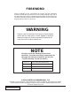
FOREWORD Proper installation of this supercharger kit requires general automotive mechanic knowledge and experience. Please browse through each step of this instruction manual prior to beginning the installation to determine if you should refer the job to a professional installer/technician. Please call Vortech Engineering for installers in your area. WARNING Extreme care must be taken when driving a supercharged vehicle with the stock clutch. If clutch slippage is detected, discontinue hard use.
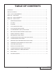
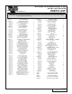
TABLE OF CONTENTS FOREWORD ..................................................................................................................................... ii TABLE OF CONTENTS .................................................................................................................... iii TOOL & SUPPLY REQUIREMENTS ................................................................................................ iv PARTS LIST - ACURA GSR ...........................................................
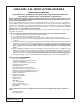
1994-2001 1.8L DOHC ACURA INTEGRA Installation Instructions Congratulations on selecting the best performing and best backed automotive supercharger available today... the VORTECH® Supercharger! Before beginning this installation, please read through this entire instruction booklet and the Street Supercharger System Owner's Manual which includes the Automotive Limited Warranties Program and the Warranty Registration form. Vortech supercharger systems are performance improving devices.
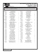
ACURA INTEGRA GSR 1.8L Part No. 4HC218-030SQ ® PARTS LIST ENGINEERING, LLC IMPORTANT: Before beginning installation, verify that all parts are included in the kit. Report any shortages or damaged parts immediately. PART # 2E129-170 DESCRIPTION QTY S/C,V-5 SQ G-TRIM CCW 1 4HC110-160 4HC010-160 7C080-056 7K312-001 7A375-100 7K375-040 S/C MOUNTING PLATE ASSY MOUNTING PLATE, 1.8 GSR 8mm x 1.25 x 55mm HHD G5 BOLT 5/16" AN-WASHER 3/8-16 x 165 HXHD PCT.
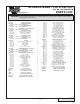
ACURA INTEGRA LS 1.8L Part No. 4HC218-060SQ ® PARTS LIST ENGINEERING, LLC IMPORTANT: Before beginning installation, verify that all parts are included in the kit. Report any shortages or damaged parts immediately. PART # 4HC110-170 DESCRIPTION QTY S/C,V-5 SQ G-TRIM CCW 1 4HC110-170 4HC010-170 7C080-056 7K312-001 7A375-100 7K375-040 4HC010-200 S/C MOUNTING PLATE ASSY MOUNTING PLATE, 1.8 LS 8mm x 1.25 x 55mm HHD G5 BOLT 5/16" AN-WASHER 3/8-16 x 165 HXHD PCT.
ACURA INTEGRA TYPE R 1.8L H.O. Part No. 4HC218-090SQ ® PARTS LIST ENGINEERING, LLC IMPORTANT: Before beginning installation, verify that all parts are included in the kit. Report any shortages or damaged parts immediately. PART # 2E129-170 DESCRIPTION S/C,V-5 SQ G-TRIM CCW QTY 1 4HC110-160 S/C MOUNTING PLATE ASSY (SEE PAGE “V” FOR INDIVIDUAL COMPONENTS) 1 4HC110-180 ASSY, HONDA MAPS BLEED (SEE PAGE “V” FOR INDIVIDUAL COMPONENTS) 1 4HC111-031 MTNG BRKT ASY, 1.
This Page Left Intentionally Blank P/N: 4HC020-030 ©2004 Vortech Engineering, LLC All Rights Reserved, Intl. Copr. Secured 28JAN04v2.1(Acura Integra LS (4HC..030v2.
1. PREPARATION/REMOVAL A. Remove the plastic pan underneath the radiator and set aside. B. Remove the strut tower brace and set aside. C. Remove the air box and all of the inlet ducting up to, but not including, the throttle body. D. Remove the valve cover breather hose, the hose connecting the water neck to the throttle body and the accompanying metal tube assembly. E. Remove the power steering belt, pump and mounting brackets. Remove the heat shield from behind the power steering pump. F.
3. OIL DRAIN A. To provide an oil drain for the supercharger, it is necessary to make a hole in the front of the oil pan. Locate and center punch the hole per Fig. 3-a. This hole should be 3/4" from bottom of oil pan lip and centered between the stiffening ribs. NOTE: B. Remove the paint around the hole. C. Use a small center punch to perforate the pan and expand the hole. Switch to a larger diameter punch and expand the hole further to approximately Ø9/16". D.
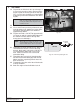
4. FUEL PUMP INSTALLATION A. Lift up and temporarily remove the rear seat cushion from the vehicle. B. Remove the three screws holding the fuel pump cover to the floor. C. Unplug the electrical connector and both fuel hoses from the fuel pump module. D. Remove the six nuts. E. Remove the fuel pump assembly from the vehicle. F. Remove the electrical connector from the fuel pump by first removing the lock. G. Disconnect the stock fuel pump from the bracket and the hose. H.
5. FUEL INJECTOR INSTALLATION A. Remove the fuel rail and fuel injectors as shown in the factory service manual. TYPE “R” H.O. KITS - Complete the following numbered steps. 1. 2. 3. 4. 5. 6. Remove the factory fuel regulator from the fuel rail. Drill the regulator supply hole in the fuel rail with an “R” (Ø.339) drill bit. Tap the hole with a 1/8" tapered pipe tap until the supplied fitting can be started. (See Fig. 5-a.) Carefully clean all of the chips out of the fuel rail.
6. FUEL MANAGEMENT UNIT (FMU) INSTALLATION A. Using the FMU mounting bracket as a template, mark and drill two holes in the firewall using Fig. 6-a as a reference for location. Mount the FMU as shown in Fig. 6-a. B. Attach the supplied 1/4" hose to the 90° barb fitting on the Vortech FMU and tighten the suppled clamp. C. Disconnect the factory fuel regulator return line from the bottom of the fuel regulator and connect to the straight fitting on the bottom of the FMU using the original clamp.(See Fig. 6b.
7. MAP SENSOR BLEED ASSEMBLY INSTALLATION A. Remove the two screws securing the Manifold Air Pressure (MAP) sensor on top of the intake manifold. B. Insert the supplied MAP sensor bleed assembly with the bleed hole positioned next to the intake manifold. The bleed hole must be down. (See Fig. 7-b.) C. Use the original O-ring between the fitting and the intake. Use the supplied O-ring between the MAP sensor and the fitting. D. Install the supplied 4mm bolts. (See Fig. 7-a).
8. POWER STEERING PLUMBING A. Select the supplied pair of power steering fittings that match the power steering pump and the metal power steering tube. The correct female fitting will fit snugly over the O-ring on the power steering tube. B. Install and lightly coat the O-ring onto the supplied power steering pump fitting with Honda power steering fluid and insert into the power steering pump. Rotate fitting until the bolt holes line up with the pump.
9. MAIN BRACKET INSTALLATION. cont’d. E. F. mounting holes in the supplied mounting bracket. Tighten to 33 ft/lbs (44 N-m). Install the supplied 2.25" idler pulley to the mounting bracket. Make sure that the spacer between the two idler pulley bearings slides over the mounting bracket pilot, secure using the supplied 5/16 x 1- 1/4" bolt and 5/16 washer. (See Fig. 9-c.) Loosely install the power steering pump using the original bolts and tensioner screw. Fig. 9-c 10.
11. SUPERCHARGER INSTALLATION A. Remove the plastic drain fitting cap and install the supplied 1/2" oil drain hose onto the barb fitting on the bottom of the supercharger and secure with the supplied #8 hose clamp. B. Install the supercharger mounting plate onto the supercharger with the three 3/8" x 1" screws as shown in Fig. 11-a. C. Install the supplied Ø5/16" x 1.0" alignment dowels into the countersunk holes in the supercharger gear case. D. Install the supplied .
11. SUPERCHARGER INSTALLATION, cont’d. G. Lower the supercharger into the engine compartment. Align the three-pin coupling on the supercharger with the three-pin coupling on the installed drive shaft assembly and connect them using the supplied composite drive coupling ring (6 holes). Verify that each set of pins is inserted into the raised bosses on their corresponding side of the composite ring. Align the holes so that one side of the pins alternate with the opposite side of pins. (See Figs. 11-d, 11-e.
12. RADIATOR HOSE AND WATER NECK INSTALLATION A1. GSR and LS Models 1. Install the supplied water neck in place of the removed factory water neck. 2. Replace the hose running from the bottom of the throttle body to the engine block/ water neck with the supplied 5/16" hose. Secure with the factory clamps. 3. Trim about 1" from the straight end of the supplied radiator hose and install. (See Fig. 12-a.) A2. Type R 1. Disconnect the upper radiator hose from the radiator. 2.
13. STANDARD KIT DISCHARGE DUCT INSTALLATION NOTE: If a high-output kit (with charge air cooler) is being installed, complete the steps included in the “Maxflow Power Cooler Installation Instructions” (P/N: 8N020-110) and then proceed with Step 14. A. Loosely install the supplied sleeves on both ends of the supplied discharge duct. The 2-3/4" to 2-1/2" reducer sleeve should be placed on the supercharger. B.
15. BYPASS VALVE INSTALLATION A. Use the supplied 1" hose to connect the bypass valve inlet to the 1" barb on the supercharger discharge tube/duct. (See Fig. 15-a.) B. Install the supplied filter onto the bypass valve discharge. C. Tighten hose clamps on each connection. D. Using supplied 5/32" vacuum line and TEE, connect barb on bypass valve to manifold vacuum. Use the manifold vacuum line connected to the fuel regulator. Fig.
16. SUPERCHARGER DRIVE BELT INSTALLATION A. Insert the keyway into the extended drive input shaft and install the pulley. Using threadlocker, install the 3/8-24 bolt through the washer and retainer and into the input shaft. The pulley retainer bolt will be tightened after the supercharger belt is installed. NOTE: Do not hammer or pry on the supercharger pulley. Heat gently with a propane torch if required for easier installation. B. Install the supercharger drive belt.
17. POWER STEERING PLUMBING/BLEEDING A. Loosely attach the power steering pressure hose to the remaining power steering fitting. With the original O-ring installed, slide the original power steering fitting into the other end of the fitting. B. Install the fitting in the receiver in the mounting bracket top plate. Use the two threaded holes in the top plate that provide the best hose routing. Secure using the supplied 1/4-20 cap screws. (See Fig. 17-a.
18. FINAL CHECK A. Make sure that all oil drain and oil feed fittings are connected and tight and that the engine is filled with factory specified oil. B. Make sure that the radiator and reservoir are full. C. Verify that the power steering reservoir is at “full cold” level. D. Cycle the fuel pump several times by turning ignition on and then off. Check all fuel system hose connections for leakage. E. With the engine running, turn the steering wheel in both directions.
19. TROUBLESHOOTING A. Supercharger belt is slipping: Belt slippage is usually accompanied by a squealing noise at high RPM and a leveling off or fluctuating boost pressure. If belt slippage occurs, tighten tensioner as follows: 1. Turn engine off. 2. Loosen the 5/16 nut on the outside of the belt tensioner plate until the tensioner stud is just loose. Loosen the jam nut on the tensioner bolt. 3. Thread in the tensioner bolt until the idler moves 1/4". 4. Tighten the nut securing the idler stud.
® ENGINEERING, LLC 1650 PACIFIC AVENUE • CHANNEL ISLANDS, CA 93033-9901 • (805) 247-0226 FAX (805) 247-0669 • www.vortechsuperchargers.com • M-F 8:00 AM - 4:30 PM PST P/N: 4HC020-030 ©2004 Vortech Engineering, LLC All Rights Reserved, Intl. Copr. Secured 28JAN04v2.1(Acura Integra LS (4HC..030v2.