Maxflow® Power Cooler ® Installation Instructions 1993 - 1997 GM LT1 Camaro and Firebird Part# 8N301-020 CARB EO# D-213-15 ® P/N: 8N020-020 © 2000 Vortech Engineering, Inc. All Rights Reserved, Intl. Copr. Secured 31JAN00 V 1.0 This product may not be legal for use on public roads in all 50 states. ENGINEERING, INC.
® ENGINEERING, INC. NOTICE This product is protected by state common law, copyright and/or patent. All legal rights therein are reserved. The design, layout, dimensions, geometry, and engineering features shown in this product are the exclusive property of Vortech Engineering, Inc.
Vortech Maxflow Power Cooler Installation Instructions 1993 - 1997 LT1 Camaro and Firebird Congratulations on selecting the best performing and most efficient aftercooler today...
FORCEPOWER® PARTS Basic Limited Warranty Vortech Forecepower parts carry a Ninety (90) Day LIMITED WARRANTY from the date of purchase from your dealer or Vortech. The part(s) must be used in the manner intended by Vortech. Any component found to be defective in either material or workmanship, will be replaced or repaired at our option, at no charge to the customer. This warranty does not included any part that is used for racing.
Vortech Maxflow Power Cooler Part No. 8N301-020 1993 - 1997 LT1 Camaro and Firebird PARTS LIST IMPORTANT: Before beginning installation, verify that all parts are included in the kit. Report any shortages or damaged parts immediately.
1. Preparation and Removal A. Disconnect the negative cable from the battery. B. Disconnect the upper (short) supercharger air bypass hose from the supercharger discharge tube and set aside. Remove both the aluminum and plastic supercharger discharge tubes from the vehicle. C. Remove the driver side exhaust manifold air injection pipe, diverter valve, tee, check valve (if equipped) and air pump discharge hose. Photo - 1 D.
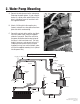
2. Water Pump Mounting A. Connect the wiring harness to the water pump. Following the photo (photo - 2) and using the bracket as a guide, mark and drill holes in the driver’s side outer frame rail and attach with the supplied hardware. B. Attach a 16GA eyelet to the negative wire (brown) and route to a clean ground free from paint and vehicle undercoating. C. Connect the red wire to the positive wire (black wire with yellow stripe) using the supplied solderless connector.
3. Water Cooler Mounting To properly mount the cooler in the limited space available, it is necessary to cut two 1-1/2” holes into the inside of the lower front bumper fascia. This will accomplish a clean secure hose route with a minimum of bends and restrictions. A. Remove the three plastic (push-in) fascia retainers that are used to attach the rear of the lower front bumper fascia to the vehicle. B. Loosely attach the supplied water cooler brackets to the cooler using the supplied 1/4” hardware.
3. Water Cooler Mounting (continued) drilled holes and supplied brackets (see photo - 4). Secure all fasteners. F. Reinstall the three plastic fascia retainers. 4 © 2000 Vortech Engineering, Inc. All Rights Reserved, Intl. Copr. Secured 31JAN00 V 1.
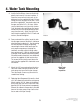
4. Water Tank Mounting A. Install all of the fittings, hoses and tank tabs onto the tank exactly as shown in photo - 5. Orient the hoses to match the hoses in the photo and use the supplied #20 and #10 hose clamps to secure the hoses to the tank. Insert one of the supplied 3/4” hose barb unions into the open end of the 3/4” x 90° hose. Make sure that both hoses each have their shorter “leg” attached to the tank fittings (the longer end of each hose should be pointing up and away from the tank).
4. Water Tank Mounting (continued) E. The open (top) end of the 1-1/4” filler hose will need to be trimmed 2-1/2” shorter so that when the hose adapter and cap are installed, the cap is near level with the top of the radiator core support. Insert the supplied aluminum hose adapter into the open end of the long 11/4” tank filler hose (this hose should have been previously routed up into the engine compartment) and secure with the supplied #20 clamp.
5. FMU Mounting A. Remount the FMU onto the passenger side valve cover in the same fashion as the original location with the fittings toward the intake manifold (see photo - 8). B. Install the new female FMU line to the vehicle. Make sure both ends of the line are secure. C. Connect the supplied length of 5/32” vacuum hose to the FMU and original manifold vacuum source. Photo - 8 New FMU location 7 © 2000 Vortech Engineering, Inc. All Rights Reserved, Intl. Copr. Secured 31JAN00 V 1.
6. Aftercooler Core A. Wrap the aftercooler core with the supplied heat blanket. Install the two supplied 1/2” NPT x 3/4” straight barb fittings into the aftercooler core using a small amount of pipe sealant onto the threads. B. Attach the supplied 90° long rubber elbows to the water fittings (the short leg of each elbow must be trimmed 1-1/4" and be installed with the short leg on the core side) on the core. Slide a hose union into the open ends of each elbow (see photo - 9).
6. Aftercooler Core (continued) the last step for pump priming. Check to ensure that the water lines are not kinked, bent or restricted in any way. 9 © 2000 Vortech Engineering, Inc. All Rights Reserved, Intl. Copr. Secured 31JAN00 V 1.
7. Discharge Tubing/Manifold AIR Injection Modification A. Place the supplied air injection adapter into the driver’s side exhaust air injection manifold port with the taper facing up (if the exhaust manifold is machined with an inverted flare seat for the air injection flare fitting, ignore this point). See Air Injection Modification diagram. If the threads in the manifold are unusually deep (such as in some aftermarket exhausts), use the supplied washers to “space” up the adapter. B.
7. Discharge Tubing/Manifold AIR Injection Modification (continued) C. Attach the supplied 90° compression fitting onto the non-flared end of the 5/8” tube and secure (the fitting should be tightened with the pipe thread end pointing toward the front of the vehicle). D. Following the Air Injection Modification diagram, cut a 2” length from the 5/8” end of the supplied 180° rubber adapter. Place the short length of hose onto the discharge side of the factory air pump.
7. Discharge Tubing/Manifold AIR Injection Modification (continued) H. Align all tubes and aftercooler core and tighten all clamps. Close the snaps located on the front of the heat sleeve/blanket. I. Using a small amount of pipe thread sealant, thread the female end of the factory diverter valve onto the supplied 90° compression fitting. J. Slide the factory air pump check valve (if equipped) into the 3/4” end of the 180° elbow previously installed onto the factory air pump.
8. Final Check A. Reconnect the battery cable. B. Temporarily remove the aftercooler return hose from the 3/4” union running to the water tank (see step 6E). C. Fill the Vortech water tank with a 25%/75% coolant/water mix until water starts to run out of the rubber return elbow located on the water tank. Temporarily insert the open end of the return hose (running from the aftercooler core) into the tank filler neck. Final Check D. Turn the ignition key to the “on” position to prime the water pump.