GM 5. 0 T.P.I. and 5.7 F Supe B o r c d h y Insta a r g e r l lation S Instruystem ction s 50 St ate S 1988-199 mog Lega 2 Model Y l per e CARB ars EO #D-21 3-17 ® ENGINEERING, LLC 1650 PACIFIC AVENUE • CHANNEL ISLANDS, CA 93033-9901 • (805) 247-0226 FAX (805) 247-0669 • www.vortechsuperchargers.com • M-F 8:00 AM - 4:30 PM PST P/N: 4GF020-010 ©2002 Vortech Engineering, LLC All Rights Reserved, Intl. Copr. Secured 12JAN01 V1.1 (88-92 350 TPI Camaro(4GF V1.
FOREWORD Proper installation of this supercharger kit requires general automotive mechanic knowledge and experience. Please browse through each step of this instruction manual prior to beginning the installation to determine if you should refer the job to a professional installer/technician. Please call Vortech Engineering for installers in your area. © 2001 VORTECH ENGINEERING, LLC All rights reserved.
Table Of Contents FOREWORD ............................................................................................................. ii TABLE OF CONTENTS ............................................................................................ iii NOTICE ..................................................................................................................... iv TOOL & SUPPLY REQUIREMENTS......................................................................... v MSD IGNITION SYSTEM .......
NOTICE This product is protected by state common law, copyright and/or patent. All legal rights therein are reserved. The design, layout, dimensions, geometry, and engineering features shown in this product are the exclusive property of Vortech Engineering,LLC.
1988 - 1992 GM 5.0 AND 5.7 F-BODY Installation Instructions 50 State Smog Legal, as per CARB EO #D-213-17 Congratulations on selecting the best performing and best backed automotive supercharger available today... the VORTECH® V-2® supercharger! Before beginning this installation, please read through this entire instruction booklet and the Street Supercharger System Owner's Manual which includes the Limited Warranty Program and the Warranty Registration form and return envelope.
SPECIAL NOTICE CONCERNING THE MSD IGNITION SYSTEM The MSD Boost Timing Master, manufactured by Autotronic Controls Corporation, included in this kit is serviced exclusively by the manufacturer. Autotronic Controls Corporation warrants this product to be free from defects in material and workmanship under normal use and if properly installed for a period of one year from the date of purchase. In case of malfunction, this unit will be repaired free of charge according to the terms of the warranty.
1988-1992 5.0 and 5.7 F-Body Part No. 4GF218-060SQ ® PARTS LIST ENGINEERING, INC. IMPORTANT: Before beginning installation, verify that all parts are included in the kit. Report any shortages or damaged parts immediately.
P/N: 4GF020-010 ©2002 Vortech Engineering, LLC All Rights Reserved, Intl. Copr. Secured 12JAN01 V1.1 (88-92 350 TPI Camaro(4GF V1.
PONTIAC SUPPLEMENTAL INSTRUCTIONS 1. RELOCATE BATTERY A. Remove the evaporative canister from the right front inner fender. Set aside for now. B. Remove the battery from its stock location at left front inner fender. Relocate battery to the right inner fender utilizing the existing factory hardware to resecure it. C. Coil and secure the excess length of positive battery cable with wire ties provided. D. Clip and extend the 8 gauge alternator wire connector with wire provided. 2.
P/N: 4GF020-010 ©2002 Vortech Engineering, LLC All Rights Reserved, Intl. Copr. Secured 12JAN01 V1.1 (88-92 350 TPI Camaro(4GF V1.
1. COMPONENT REMOVAL A. Disconnect the battery (negative lead). B. Remove and set aside the following components: • Air inlet bellows • Air filter cover assembly and elements and the panel below filter • Windshield washer reservoir • Accessory drive belt • Crankshaft pulley • Alternator (disconnect wiring) • Power steering pump pulley (use puller) • Power steering pump and bracket (DO NOT disconnect lines) • Power steering bracket 2. CRANKSHAFT PULLEY INSTALLATION A.
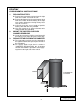
3. OIL DRAIN LINE A. Raise the front of the vehicle and support with appropriate jack stands. B. To provide an oil drain for the supercharger, it is necessary to make a hole in the oil pan. It is best to punch the hole rather than drill. OIL PAN Remove paint around the hole area so that it does not flake into the pan. C. Make a mark on the oil pan on the driver’s side ahead PUNCH HOLE THROUGH of the oil filter. The mark should be 3" below the third bolt from the rear of the pan. D.
4. OIL FEED LINE A. The supercharger uses engine oil for lubrication and must have an oil feed line connected to a filtered oil access on the engine and an oil return or drain. The return is a gravity drain and should be routed so a gradual drop is provided and connected to the oil pan above oil level and away from suspension components or exhaust headers or pipes. ENGINE BLOCK TIE WRAPS CLAMPS OIL PAN WARNING: The oil system contains a small orifice that is easily plugged.
5. AUXILIARY FUEL PUMP A. Open the fuel fill cap briefly to vent any pressure. Find the stock 3/8" fuel feed line near the front of the engine's left valve cover. B. Cut the stock hose approximately 7" from the fitting nearer the engine and fit the new hose with the "splice fitting" into the engine end and secure with a clamp. C. Place the other end of the new hose on the pump outlet fitting (brass fitting) and secure with a clamp. D.
6. FUEL MANAGEMENT UNIT INSTALLATION A. Mount the fuel management unit (FMU) to the inner fender on the driver's side. Placement should be on the vertical flat area near the top of the fender above and just rearward of the horn assemblies. Using the FMU mounting bracket as a template, mark and drill two 3/32" holes. Use the sheet metal screws in the kit to secure. B. It is necessary to plumb the FMU into the fuel return line. Start by cutting the fuel return line 7" from the end at the engine. C.
7. MAIN BRACKET AND POWER STEERING PUMP A. Temporarily install the main bracket on the engine using two of the 3/8-16 x 5 1/2" bolts as pilots to position the bracket to the cylinder head. Remove the fuel line bracket and carefully bend the fuel lines as necessary to permit bracket installation. B. Install the flat head socket bolt in the chamferred hole and secure to 32 ft/lb torque. C.
8. SUPERCHARGER MOUNTING A. Attach the supercharger drain hose to the fitting on the bottom of the supercharger and secure with the clamp provided. Make sure the clamp is rotated so that it will not interfere with the mounting plate when installed. B. Mount the supercharger to the mounting plate with the five 3/8-16 x 1" bolts and washers as shown and tighten to 24 ft./lb. C. Attach the oil feed line and secure. Use only oil and no sealants. D.
9. CANISTER RELOCATION A. Remove the plastic splash panel in front of the left front tire (panel is secured by two bolts and two snaps). 1-1/4" B. Remove hose from between evaporative canister and 'Y' fitting. Replace with 15" long hose. C. Remove the hose between the evaporative canister and the throttlebody. Replace 3-1/2" with 23" long hose. D. Disconnect the solenoid wire from the canister and extend it 12" with the wire provided. E.
11. AIR FILTER, INLET DUCT AND DISCHARGE PLENUM A. Locate the new air filter on the flat area to the rear of the left headlight and secure through the end of the filter to the panel floor with the bolt and washer provided. B. Use the three plastic elbows, wide blue sleeves and 3 1/2" flex tube to connect the air filter to the supercharger inlet as shown in the photo in section 14 and secure with the hose clamps provided. Do not overtighten the clamps.
12. WINDSHIELD WASHER RESERVOIR A. Fit the supplied washer reservoir in the area behind the grill on the radiator core support (inward of the driver's side headlight). Use the hardware in the kit to secure the reservoir in place. B. Secure the washer pump with the Adel clamp provided to the flat area next to the new fuel pump. C. Extend the inlet hose from the pump to the reservoir outlet and fill the reservoir with fluid. 13. IGNITION/BOOST CONTROL INSTALLATION A.
13. IGNITION/BOOST CONTROL INSTALLATION, cont'd. E. Using the wire splice connector provided, connect the red wire to the pink wire located between the distributor and coil. Use the short extension wire provided. F. Connect the vent to manifold pressure. G. Route the Ignition/Boost Control wires through the firewall from the interior side. Mount the knob in an easily accessible place. H.
15. FINAL ASSEMBLY AND CHECK OVER A. Reconnect the battery. B. If your vehicle has gone over 10,000 miles since its last spark plug change, you will need to change the spark plugs now before test driving the vehicle. C. Check all fittings, nuts, bolts and clamps for tightness. Pay particular attention to oil and fuel lines around moving parts, sharp edges and exhaust system parts. Make sure all wires and lines are properly secured with clamps or tie wraps. D.