
User's Manual


P/N: 4NT020-010
©2007 Vortech Engineering, LLC
All Rights Reserved, Intl. Copr. Secured
09JUN07 v1.1 NissanTitan(4NTv1.1)
8
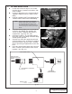
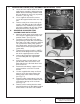
A. DISCHARGE ASSEMBLY INSTALLATION:
1. Cut a 2" piece off the long end of the sup-
plied Ø1.0" x 90° hose.
2. Attach the inlet of the bypass valve to the
bung on the charge cooler.
3. Trim the long leg of the supplied 90° hose
down to 5-1/2" long and attach to the dis-
charge of the bypass valve. (See Fig. 7-a.)
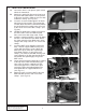
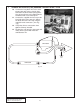
4. Install the 1/2"NPT fittings into the charge
air cooler using thread sealant as shown.
(See Fig. 7-b.)
5. Use the Ø2.75" x 3" long sleeve to con-
nect the inlet of the charge cooler to the
supercharger discharge.
6. Attach the 90° hose from the bypass
valve discharge to the bung on the super-
charger inlet elbow. Tighten the #16 hose
clamps on all bypass valve connections.
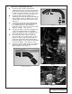
7. Using the Ø2.75" x 2" long sleeve on the
discharge of the charge cooler, connect
the 90° discharge tube to the throttle body
with the Ø3.25" x Ø2.75" x 90° reducer
elbow.
8. Position the discharge assembly so that
there is no contact with brake lines, inlet
duct or the hood and tighten the hose
clamps. (See Fig. 7-c.)
B. SURGE TANK INSTALLATION:
1. Install a 3/4" barb x 90° fitting in the bot-
tom of the supplied CAC surge tank.
Install a straight fitting in the topmost hole
of the plastic CAC surge tank. Using a 2"
length of Ø3/4" hose, connect the straight
fitting in the surge tank to the 90° fitting
installed into the top of the charge cooler.
2. Secure the surge tank to the bracket on
the charge cooler using 1/4-20 x 1/2" long
bolts.
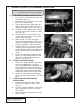
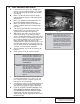
C. CHARGE AIR COOLER RADIATOR
INSTALLATION:
1. Install two 1/2"NPT x 90° brass fittings
into the CAC radiator as shown. (See
Fig. 7-d.)
2. Using the supplied hardware, connect the
upper bracket to the driver’s side of the
CAC radiator.
3. Attach the lower bracket to the CAC radi-
ator as shown.
7. CHARGE AIR COOLER (CAC) ASSEMBLY INSTALLATION
Fig. 7-a
Fig. 7-b
Fig. 7-c
NOTE: Make sure all CAC water hoses are routed
smoothly and have no kinks or sharp bends.