2004Nissa 2006 n Tita Supe n rcha In rger S stalla tion I ystem 50 Sta n struc te Sm og Leg al Per tions CARB EO #D -213-2 5 ® ENGINEERING, LLC 1650 Pacific Avenue, Channel Islands CA 93033-9901 • Phone: 805 247-0226 Fax: 805 247-0669 • www.vortechsuperchargers.com • M-F 8:00AM - 4:30PM (PST) DP/N: 4NT020-010 - v1.
FOREWORD his manual provides information on the installation, maintenance and service of the Vortech supercharger kit expressly designed for this vehicle. All information, illustrations and specifications contained herein are based on the latest product information available at the time of this publication. Changes to the manual may be made at any time without notice.
TABLE OF CONTENTS FOREWORD . . . . . . . . . . . . . . . . . . . . . . . . . . . . . . . . . . . . . . . . . . . . . . . . . . . . . . . .ii TABLE OF CONTENTS . . . . . . . . . . . . . . . . . . . . . . . . . . . . . . . . . . . . . . . . . . . . . . . .iii IMPORTANT NOTES . . . . . . . . . . . . . . . . . . . . . . . . . . . . . . . . . . . . . . . . . . . . . . . . . .iv TOOL & SUPPY REQUIREMENTS . . . . . . . . . . . . . . . . . . . . . . . . . . . . . . . . . . . . . . .
2004-2006 Nissan Titan NOTICE This product is protected by state common law, copyright and/or patent. All legal rights therein are reserved. The design, layout, dimensions, geometry, and engineering features shown in this product are the exclusive property of Vortech Engineering, LLC.
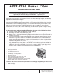
2004-2006 Nissan Titan Installation Instructions Congratulations on selecting the best performing and best backed automotive supercharger available today... the VORTECH® supercharger! Before beginning this installation, please read through this entire instruction booklet and the Street Supercharger System Owner’s Manual which includes the Limited Warranty Program, the Warranty Registration form and return envelope. Vortech supercharger systems are performance improving devices.
2004-2006 Nissan Titan Part No. 4NT218-010SQ ® PARTS LIST ENGINEERING, LLC IMPORTANT: PART NO.
1. PREPARATION/REMOVAL NOTE: A. B. C. D. E. F. G. H. I. J. K. L. Beginning the supercharger installation with less than 1/8" a tank will make changing the fuel pump easier. Disconnect the Battery. Remove the engine cover. Remove the engine cover bracket located above the throttle body. Remove the wiring harness bracket from above the driver’s side valve cover.
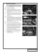
2. FUEL INJECTOR REPLACEMENT A. B. C. D. E. F. G. H. I. J. Relieve the fuel system pressure. Disconnect the eight fuel injector plugs and retaining clips from the injectors. Install the factory injector retaining clips onto the new injectors. Remove the four screws that hold down the fuel rail to the intake manifold. Lift up on the rails evenly and remove all eight injectors Using a small amount of clean motor oil, lightly lubricate the O-rings on both ends of the Vortech supplied fuel injectors.
3. MOUNTING BRACKET/SUPERCHARGER INSTALLATION A. B. C. D. E. F. G. H. I. J. K. L. Locate the driver’s side cam cover. Remove the eight 6mm screws and carefully pry the cover from the cylinder head. (See Fig. 3-a.) Clean any excess sealant from the mating surface on the cam sprocket housing. Install the supplied 3/8"NPT x 1/2" barb x 90° fitting into the 3/8"NPT hole in the supplied supercharger mounting plate.
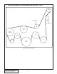
3. MOUNTING BRACKET/SUPERCHARGER INSTALLATION, cont’d S/C PULLEY SUPPLIED IDLER SUPPLIED IDLER WATER PUMP POWER STEERING FAN TENSIONER A/C ALT CRANK PULLEY Fig. 3-e | Belt Routing Diagram P/N: 4NT020-010 ©2007 Vortech Engineering, LLC All Rights Reserved, Intl. Copr. Secured 09JUN07 v1.1 NissanTitan(4NTv1.
4. OIL FEED INSTALLATION A. B. C. Locate and remove the oil pressure sender from the oil pan. (Located to the driver’s side of the oil filter.) In place of the oil pressure sender, install the supplied 1/8"BSPT male to 1/8"NPT female fitting. Insert the supplied 1/8"NPT street fitting into the 1/8"NPT female section of the installed fitting. NOTE: D. E. F. G. Use only clean engine oil on the pipe threads.
5. INLET DUCT INSTALLATION A. B. C. D. E. F G. H. Loosen the driver’s side plastic splash shield above the front wheel. Attach the supplied air filter to the long leg of the plastic 90° elbow. Attach a 2" long sleeve to the open end of the elbow and secure with a #56 hose clamp. (See Fig. 5-a.) Insert the sleeved end through the air intake hole from the inner fender. (This locates the air filter above the driver’s side wheel).
6. COOLANT LINE MODIFICATION A. B. C. D. E. F. Locate the upper factory radiator hose (Referenced as Hose “A”) that connected the plastic thermostat housing to the hard radiator tube removed in Section 1. Using Fig. 6-a, cut 2.5" sections from each end of the hose. Locate the lower factory radiator hose (Referenced as Hose “B”) that connected the lower radiator port to the bottom of the hard radiator tube. Use Fig. 6-b to cut the hose in two places.
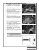
7. CHARGE AIR COOLER (CAC) ASSEMBLY INSTALLATION NOTE: Make sure all CAC water hoses are routed smoothly and have no kinks or sharp bends. A. DISCHARGE ASSEMBLY INSTALLATION: 1. Cut a 2" piece off the long end of the supplied Ø1.0" x 90° hose. 2. Attach the inlet of the bypass valve to the bung on the charge cooler. 3. Trim the long leg of the supplied 90° hose down to 5-1/2" long and attach to the discharge of the bypass valve. (See Fig. 7-a.) 4.
7. CHARGE AIR COOLER (CAC) ASSEMBLY INSTALLATION, cont’d 4. Locate the CAC radiator between the two angled cross members, lining up the two bottom bracket mounting locations. Bend the horn bracket as necessary to provide clearance. (See Fig. 7-d.) 5. Use a supplied sheet metal screw to secure the upper bracket to the core support. 6. Connect a 48" piece of hose to the passenger’s side fitting on the CAC radiator.
7. CHARGE AIR COOLER (CAC) ASSEMBLY INSTALLATION, cont’d 10. Connect the long black wire to the water pump power wire using a female slide connector. Route the water pump power wire up to and across the cowl below the windshield and secure with zip-ties. 11. Connect the supplied mini fuse tap to the load side of the fuel pump fuse. Attach the black wire to the fuse tap using the supplied female connector. (See Fig. 7-g.) 12. Verify that all hose connections have tightened clamps installed. 13.
8. PIGGYBACK ENGINE CONTROL UNIT (ECU) INSTALLATION A. Install the supplied “piggyback ECU” per the instructions supplied with the unit. NOTE: There is no “accessory cable functionality” used with the supercharger kit and it should be removed from the ECU if equipped. Fig. 8-a 11 P/N: 4NT020-010 ©2007 Vortech Engineering, LLC All Rights Reserved, Intl. Copr. Secured 09JUN07 v1.1 NissanTitan(4NTv1.
9. IN-TANK-FUEL PUMP INSTALLATION NOTE: 1. 2. 3. 4. Making sure that the vehicle has only a small amount of fuel in the tank will make the fuel tank easier to maneuver. Disconnect the fuel lines (including the fuel filler hose) and electrical connector(s) from the fuel tank. Remove the fuel tank from the vehicle. Remove the fuel pump module from the tank by rotating the clamp ring. Remove the factory fuel pump. Install the supplied fuel pump in its place.
10. A. B. C. D. E. F. G. H. FINAL ASSEMBLY AND CHECK If your vehicle has gone over 20,000 miles since its last spark plug change, it is a good idea to change the spark plugs now, before test-driving. Make sure that oil drain to oil pan fitting is tight and that the engine is filled with factory specified oil. Make sure radiator and overflow tanks are filled with a 50/50 coolant/water mix. Make sure that the vehicle is filled with 91 octane or higher fuel before commencing a test drive.
® ENGINEERING, LLC 1650 Pacific Avenue, Channel Islands CA 93033-9901 • Phone: 805 247-0226 Fax: 805 247-0669 • www.vortechsuperchargers.com • M-F 8:00AM - 4:30PM (PST) DP/N: 4NT020-010 - v1.