GM 7. 4 Ligh Supe t Truck r c harge Insta r Sys llatio t n Ins truct em ions 50 St ate S 1988-199 mog Lega 5 Model Y l per e CARB ars EO #D-21 3-17 ® ENGINEERING, LLC 1650 PACIFIC AVENUE • CHANNEL ISLANDS, CA 93033-9901 • (805) 247-0226 FAX (805) 247-0669 • www.vortechsuperchargers.com • M-F 8:00 AM - 4:30 PM PST P/N: 4GC020-010 ©2001 Vortech Engineering, LLC All Rights Reserved, Intl. Copr. Secured 15SEP01 V1.
FOREWORD Proper installation of this supercharger kit requires general automotive mechanic knowledge and experience. Please browse through each step of this instruction manual prior to beginning the installation to determine if you should refer the job to a professional installer/technician. Please call Vortech Engineering for installers in your area. © 2001 VORTECH ENGINEERING, LLC All rights reserved.
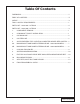
Table Of Contents FOREWORD ...................................................................................................................... ii TABLE OF CONTENTS ..................................................................................................... iii NOTICE .............................................................................................................................. iv TOOL & SUPPLY REQUIREMENTS ...........................................................................
NOTICE This product is protected by state common law, copyright and/or patent. All legal rights therein are reserved. The design, layout, dimensions, geometry, and engineering features shown in this product are the exclusive property of Vortech Engineering, Inc.
1988 - 1995 GM 7.4 LIGHT TRUCK Installation Instructions 50 State Smog Legal, as per CARB EO #D-213-17 Congratulations on selecting the best performing and best backed automotive supercharger available today... the VORTECH® V-2® Supercharger! Before beginning this installation, please read through this entire instruction booklet and the Street Supercharger System Owner's Manual which includes the Limited Warranty Program and the Warranty Registration form and return envelope.
P/N: 4GC020-010 ©2001 Vortech Engineering, LLC All Rights Reserved, Intl. Copr. Secured 15SEP01 V1.
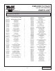
1988-1993 7.4 Truck Part No. 4GC218-090SQ ® PARTS LIST ENGINEERING, LLC IMPORTANT: Before beginning installation, verify that all parts are included in the kit. Report any shortages or damaged parts immediately.
P/N: 4GC020-010 ©2001 Vortech Engineering, LLC All Rights Reserved, Intl. Copr. Secured 15SEP01 V1.
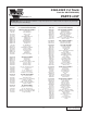
1994-1995 7.4 Truck Part No. 4GG218-090SQ ® PARTS LIST ENGINEERING, LLC IMPORTANT: Before beginning installation, verify that all parts are included in the kit. Report any shortages or damaged parts immediately.
P/N: 4GC020-010 ©2001 Vortech Engineering, LLC All Rights Reserved, Intl. Copr. Secured 15SEP01 V1.
1. COMPONENT REMOVAL A. Disconnect the battery (negative lead). B. Remove and set aside the following components: • The top portion of the fan shroud • The accessory drive belt • The cooling fan assembly • The crankshaft pulley • The air filter canister assembly and hose • The intake air resonator (detach from inner fender) • The power steering pump pulley (1994 models only) NOTE: If the vehicle is a 1993 model year or later, it will be necessary to purchase the stock air inlet resonator.
3. OIL DRAIN LINE A. Raise the front of the vehicle and support with appropriate jack stands. B. To provide an oil drain for the supercharger, it is necessary to make a hole in the oil pan. It is best to punch the hole rather than drill. Remove paint around the hole area so that it does not flake into the pan. C. Make a mark on the oil pan on the driver’s side ahead of the oil filter. The mark should be 3" below the bolt flange and rearward of the fourth bolt 7/8". (See Fig. 3-a.
4. OIL FEED LINE A. The supercharger uses engine oil for lubrication and must have an oil feed line connected to a filtered oil access on the engine and an oil return or drain. (See Fig. 4-a.) Connection to the oil pan must be above the oil level. WARNING: The oil system contains a small orifice that is easily plugged. DO NOT use any type sealant on any feed line threads. Instead, use clean engine oil. Disassemble and blow out entire line if you have any doubts. B.
5. SUPPLEMENTARY FUEL INJECTION COMPUTER AND RELATED SYSTEM - Cont'd. NOTE: Make sure all small holes are aligned and not plugged with gasket sealer when installed. D. Mount the additional fuel pump to the inner side of the frame rail beneath the driver's side floor. Use the shorter hose provided to help locate the pump the correct distance from the filter. This hose has an adapter fitting on the filter end. Secure the pump to the frame and hose with the clamp and fastener provided. (See Fig. 5-a.) E.
5. SUPPLEMENTARY FUEL INJECTION COMPUTER AND RELATED SYSTEM - Cont'd. NOTE: Factory fuel return line must be attached to original fitting on TBI unit.
5. SUPPLEMENTARY FUEL INJECTION COMPUTER AND RELATED SYSTEM - Cont'd. TEMPLATE THROTTLE BODY DRILL TWO HOLES THROUGH BOTTOM OF THROTTLE BODY UNTIL POSITIVE THROTTLE SHAFT CONTACT USE 3/64" OR #56 (.046) DIAMETER .100 .100 4.550 Fig. 6A-a P/N: 4GC020-010 ©2001 Vortech Engineering, LLC All Rights Reserved, Intl. Copr. Secured 15SEP01 V1.
6A. MAIN BRACKET AND POWER STEERING PUMP - 1988-1993 MODELS A. Install the connector bracket to the front of the stock bracket at the power steering pump with the two longer metric fasteners provided. Some vehicles use metric and others use standard SAE threads. Check the threads on the fasteners you have just removed against the ones supplied prior to installation. Both metric and standard fasteners have been provided for your convenience. Leave the fasteners slightly loose until all fasteners are started.
6B. MAIN BRACKET AND POWER STEERING PUMP 1994 - 1995 MODELS ONLY A. Disconnect all electrical connections at the alternator. B. Remove the alternator from the vehicle and set aside. C. Loosen the main cast iron accessory mounting bracket. D. Remove the power steering pump fasteners and set pump aside temporarily. Remove mounting bracket. E. Locate the power steering pump into the supplied mounting bracket. Install the two right side bolts finger tight. F.
6B. MAIN BRACKET AND POWER STEERING PUMP 1994 - 1995 MODELS ONLY, Cont'd. FACTORY ALTERNATOR BOLT ALTERNATOR ATTACHMENT PLATE SPACER 'A' 1.895 SPACER 'B' 1.083 3/8-16 X 3" POWER STEERING PUMP MOUNTING FLANGE 1" SPACER 7/16-14 X 5-3/4" SPACER C, .22" FACTORY POWER STEERING PUMP BOLT 3/8-16 3/8-16 xX2-3/4" 2-1/4" STAINLESS STAINLESS STEEL BOLT BOLT STEEL SUPPORT ROD 3/8-16 X 1" BOLT, AN 3/8" WASHERS 3/8-16Xx1-1/2" 2" 3/8-16 FOR 1994-1995 MODELS ONLY Fig. 6B-a 7. COOLING FAN SPACER A.
8. SUPERCHARGER MOUNTING A. Attach the supercharger drain hose to the fitting on the bottom of the supercharger and secure with the clamp provided. Make sure to rotate the clamp so it does not interfere with the mounting plate. B. Mount the supercharger to the mounting plate with the four 3/8 16 x 1" bolts and washers and one 3/8-16 x 1-1/4" bolt and washer for the plate stiffener (See Fig. 8-a.) (For 1994-95 models, the supercharger is mounted with five 3/8-16 x 1" bolts and washers only.
10. DISCHARGE PLENUM A. Thread the supplied 90° plastic fitting into the 3/4 NPT bung located on the discharge plenum. (The fitting should be screwed in until snug, pointing down & to the right at approximately a 45° angle.) B. Attach the discharge tube between the plenum and supercharger with blue sleeves; secure with clamps as shown. C. Install the short 1" hose piece onto the 90° fitting with hose clamps.
11. AIR FILTER, INLET DUCT AND PLENUM NOTE: On model years 1993 and later, it will be necessary to replace the resonator unit with the earlier type prior to modifying. The Chevrolet part number is 25097949. A. Modify the stock resonator chamber by cutting off the end at the point where the radius stops. (See Fig. 11-a.) B. Remove the internal baffle tube and deburr the cut edge. C. Fit the new end cover, with the air filter element provided, over the end of the modified resonator.
12. FINAL REASSEMBLY & CHECK A. Refit the upper fan shroud. B. Reconnect the battery. C. If your vehicle has gone over 10,000 miles since its last spark plug change, you will need to change the spark plugs now before test driving the vehicle. D. Check all fittings, nuts, bolts and clamps for tightness. Pay particular attention to oil and fuel lines around moving parts, sharp edges and exhaust system parts. Make sure all wires and lines are properly secured with clamps or tie wraps. E.
® ENGINEERING, LLC 1650 PACIFIC AVENUE • CHANNEL ISLANDS, CA 93033-9901 • (805) 247-0226 FAX (805) 247-0669 • www.vortechsuperchargers.com • M-F 8:00 AM - 4:30 PM PST P/N: 4GC020-010 ©2001 Vortech Engineering, LLC All Rights Reserved, Intl. Copr. Secured 15SEP01 V1.