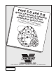
Ford 5.0 a n o/F-S eries d 5.8 Supe /Lig rc Bronc harge h tning r S llatio n Ins ystem truct ions Insta ’87-’96 5.8L FSeries ’93-’95 Truck 5.8L Lig 50 State h tning T ’87-’96 Smog L ruck - 5 5.0L Fegal pe 0 State Series r CARB Smog L Truck EO #Degal pe 50 State 213-16 r CARB E Smog L O #D-2 egal pe 13-16 r CARB EO #D213-16 ® ENGINEERING, INC. 1650 PACIFIC AVENUE • CHANNEL ISLANDS, CA 93033-9901 P/N: 4FC020-010 ©2000 Vortech Engineering, Inc. All Rights Reserved, Intl. Copr. Secured 13SEP00 V1.
FOREWORD Proper installation of this supercharger kit requires general automotive mechanic knowledge and experience. Please browse through each step of this instruction manual prior to beginning the installation to determine if you should refer the job to a professional installer/technician. Please call Vortech Engineering for possible installers in your area. © 2000 VORTECH ENGINEERING, INCORPORATED All rights reserved.
Table Of Contents FOREWORD ........................................................................................................................... i TABLE OF CONTENTS .......................................................................................................... ii IMPORTANT NOTICES .......................................................................................................... iii CRANE IGNITION SYSTEMS ..............................................................................
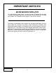
IMPORTANT NOTICES! BEFORE BEGINNING INSTALLATION On 1993 and later model years, it will be necessary to replace the fan blade assembly (not the entire fan clutch assembly) with an earlier model unit. The Ford part number is E7TZ-8600B. Refer to page 5, item 8 of this manual. This product is protected by state common law, copyright and/or patent. All legal rights therein are reserved.
SPECIAL NOTICE CONCERNING THE CRANE IGNITION SYSTEM The ignition system, manufactured by Crane Electronics, included in this kit is serviced exclusively by the manufacturer. Crane Electronics warrants this product to be free from defects in material and workmanship under normal use and if properly installed for a period of one (1) year from the date of purchase. In case of malfunction, this unit will be repaired free of charge according to the terms of the warranty.
SPECIAL NOTICE CONCERNING THE MSD IGNITION SYSTEM The MSD Boost Timing Master, manufactured by Autotronic Controls Corporation, included in this kit is serviced exclusively by the manufacturer. Autotronic Controls Corporation warrants this product to be free from defects in material and workmanship under normal use and if properly installed for a period of one (1) year from the date of purchase. In case of malfunction, this unit will be repaired free of charge according to the terms of the warranty.
Installation Instructions for ’87-’96 5.8L F-Series Truck - 50 State Smog Legal per CARB EO #D-213-16 ’93-’95 5.8L Lightning Truck - 50 State Smog Legal per CARB EO #D-213-16 ’87-’96 5.0L F-Series Truck - 50 State Smog Legal per CARB EO #D-213-16 Congratulations on selecting the most technically innovative, best performing and best backed automotive supercharger available today...
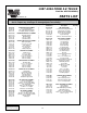
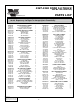
1987-1996 FORD 5.8 TRUCK Part No. 4FC218-030SQ ® PARTS LIST ENGINEERING, INC. IMPORTANT: Before beginning installation, verify that all parts are included in the kit. Report any shortages or damaged parts immediately. Part Number Description 2E228-030 2E128-030 2A036-287 8R101-001 SUPERCHARGER ASSEMBLY V-2 SQ Supercharger 2.
1993-1995 FORD 5.8 LIGHTNING TRUCK Part No. 4FC218-040SQ ® PARTS LIST ENGINEERING, INC. IMPORTANT: Before beginning installation, verify that all parts are included in the kit. Report any shortages or damaged parts immediately. Part Number Description Quantity Part Number Description Quantity 2E228-130 2E128-030 2A036-287 8R101-001 SUPERCHARGER ASSEMBLY V-2 SQ Supercharger 2.
1987-1996 FORD 5.0 TRUCK Part No. 4FE218-070SQ ® PARTS LIST ENGINEERING, INC. IMPORTANT: Before beginning installation, verify that all parts are included in the kit. Report any shortages or damaged parts immediately. Part Number Description 2E228-030 2E128-030 2A036-312 8R101-001 SUPERCHARGER ASSEMBLY V-2 SQ Supercharger 3.
1. COMPONENT REMOVAL A. Remove the following: 1. intake air duct 2. air filter box cover & inlet hoses 3. accessory drive belt 4. cooling fan & fan shroud 5. water pump pulley 6. crank pulley 7. power steering pulley (using a pulley) B. Remove the A/C compressor from the mounting bracket and secure to one side. NOTE: When removing the power steering pump and A/C compressor, do not break any lines; just set the unit aside. C. Remove the power steering pump from the bracket. D.
3. 4. OIL DRAIN FITTING A. Remove the driver's side valve cover. B. Measure 4-3/4" forward from the middle of the center bolt hole and up 3/4" from the flange as shown on the inboard side of the valve cover and mark. (See Figure 3-a.) C. Make an 11/16" diameter hole at the mark using a drill or chassis punch. Debur the hole completely. Thoroughly clean the valve cover. D. Install the 1/2" hose fitting into the elbow and tighten. E.
5. MAIN BRACKET INSTALLATION, CONT'D. D. Reinstall the power steering pump pulley. Make sure that the pulley is properly placed on the pump shaft so that the end of the shaft and the front face of the pulley hub are flush. NOTE: For proper accessory drive belt alignment, it is imperative that the power steering pump pulley be reinstalled properly. There should be no recess nor should there be any protrusion of the shaft. It must be FLUSH. 6. SUPERCHARGER INSTALLATION A.
7. OUTLET PLENUM DISCHARGE TUBE A. Temporarily place the 2 3/4" diameter blue sleeve on the supercharger outlet as far as it will go. NOTE: If installing the kit on a 5.8 Lightning, disregard points B, C and D. Install the discharge tube to the throttle body using the 3" x 2" sleeve and the clamps provided. (See Figures 7-a, 7-b.) B. Slide the two 2" diameter blue sleeves onto the throttle body inlets, temporarily, as far as they will go.
8. WATER PUMP PULLEY AND FAN ASSEMBLY NOTE: On 1993 and later model years, it will be necessary to replace the fan blade assembly (not the entire fan clutch assembly) with an earlier model unit. The Ford part number is E7TZ-8600B. A. Screw the four 5/16" studs into the water pump flange. B. Place the Vortech supplied water pump pulley onto the studs. C. Lower the fan assembly and fan shroud into place together. D. Secure the fan assembly onto the water pump with the nuts and the washers provided. E.
10. FUEL PUMP A. Release any pressure from the fuel tank by momentarily loosening the filler cap. B. Disconnect the line to the fuel filter by carefully removing the white retaining tab. Attach the line to the adapter fitting, as shown. (See Figure 10-a.) C. Connect the fuel pump inlet to the adapter with the 3/8" hose provided. D. Connect the fuel pump outlet to the filter inlet with the 5/16" hose. Use the supplied Ford fuel connector and hose clamp. E.
11. FUEL MANAGEMENT UNIT INSTALLATION CONNECT TO MANIFOLD VACUUM/PRESSURE INLET (FUEL LINE FROM STOCK REGULATOR) OUTLET (FUEL FROM HERE RETURNS TO TANK) Figure: 11-a BYPASS VALVE (LIGHTNING ONLY) MANIFOLD VACUUM TREE NOTE: Make sure you have routed all fuel lines away from all moving parts, sharp edges, exhaust pipes and manifolds. Secure the fuel lines with the tie wraps and hose clamps provided. FMU TOP VIEW E.
12. AIR FILTER COVER AND INLET DUCT A. Secure the Vortech air filter cover in place of the stock air filter cover with the original screws. Replace or clean the air filter element, if necessary. IMPORTANT: For the 94-96 5.0 and 95-96 5.8, disregard step A and complete the following steps before proceeding to step B. 1. Remove the air filter cover/MAF assembly. Drill a 7/8" hole into the rear portion of the cover (the side facing the brake master cylinder).
13. 5.8 LIGHTNING SUPPLEMENTAL INSTALLATION INSTRUCTIONS FOR THE BYPASS VALVE A. Screw the fitting into the new inlet elbow as shown in the graphic. B. Install the inlet elbow onto the supercharger with the fitting on top and pointing towards the small tube branched off of the discharge tube. C. Place the hoses, as shown, on the valve and secure with the clamps provided. D. Install the valve with the hoses connected, between the inlet elbow and discharge tube. Secure hoses with the clamps. E.
14.1 IGNITION/BOOST CONTROL UNIT INSTALLATION (NON-LIGHTNING TRUCKS ONLY), CONT'D. TO MANIFOLD VACUUM BOOST RETARD 2 1 BOOST RETARD CONNECTOR 0 3 GROUND BLACK ® SUPERCHARGERS Ignition/Boost Control MANUFACTURED FOR VORTECH SUPERCHARGERS BY MSD MAGNETIC PICKUP CONNECTOR (NOT USED) IGNITION COIL WHITE RED ORANGE BLACK FROM FACTORY COIL HARNESS Figure: 14-b P/N: 4FC020-010 ©2000 Vortech Engineering, Inc. All Rights Reserved, Intl. Copr. Secured 13SEP00 V1.3 (86-93 5.
14.2 IGNITION/BOOST CONTROL UNIT INSTALLATION (LIGHTNING TRUCKS ONLY) A. Mount the main ignition box under the hood in a location that will keep the unit as cool and dry as possible. Use the supplied sheet metal screws to secure. B. Route the heavy black cable to a clean ground. Route the heavy red cable to the (+) positive battery terminal. C. Install the ignition/boost retard wiring harness following Figure 14A-a. D. Mount the retard adjustment knob in an easily accessible position from the driver's seat.
15. IGNITION/BOOST CONTROL UNIT OPERATION A. The Ignition/Boost Control unit is designed to retard ignition in relation to boost. B. The unit is adjustable from 0° to 4°of ignition retard for each pound of boost, up to a maximum of 20°. (See Figure 15-a.) C. Using the 1° per pound position as a starting place, adjust the ignition retard knob until just beyond the point of detonation. Use third gear for testing in a safe area or road. Adjust the retard according to changes in altitude and fuel quality.
16. FINAL CHECK WARNING: Do not attempt to operate the vehicle until ALL components are installed and ALL operations are completed including the final check. A. Reconnect the battery. B. If your vehicle has gone over 10,000 miles since its last spark plug change, you will need to change the spark plugs now before test driving the vehicle. C. Check all fittings, nuts, bolts and clamps for tightness. Pay particular attention to oil and fuel lines around moving parts, sharp edges and exhaust system parts.
® ENGINEERING, INC. 1650 Pacific Avenue, Channel Islands, CA 93033-9901 • (805) 247-0226 FAX (805) 247-0669 • vortechsuperchargers.com • M-F 8:00AM - 4:30PM (PST) P/N: 4FC020-010 ©2000 Vortech Engineering, Inc. All Rights Reserved, Intl. Copr. Secured 13SEP00 V1.3 (86-93 5.