F Exploord 4.0L Supe rer/R Insta rcharger anger llat Sy stem ion In struc tions FORD EXP 50 STFORD RA LORER 19 NG ATE S 9 MOG ER 1990 1-1994 MO -1 LEGA D L AS 994 MODE EL YEAR PER C S L ARB YEARS EO #D -21317 ® ENGINEERING, LLC 1650 PACIFIC AVENUE • CHANNEL ISLANDS, CA 93033-9901 • (805) 247-0226 FAX (805) 247-0669 • www.vortechsuperchargers.com • M-F 8:00 AM - 4:30 PM PST P/N: 4FD020-010 ©2001 Vortech Engineering, LLC All Rights Reserved, Intl. Copr. Secured 31JUL01 V1.1(Explorer/Ranger(4FD V1.
FOREWORD Proper installation of this supercharger kit requires general automotive mechanic knowledge and experience. Please browse through each step of this instruction manual prior to beginning the installation to determine if you should refer the job to a professional installer/technician. Please call Vortech Engineering for installers in your area. © 2001 VORTECH ENGINEERING, LLC All rights reserved.
Table Of Contents FOREWORD ...................................................................................................................... ii TABLE OF CONTENTS ..................................................................................................... iii TOOL & SUPPLY REQUIREMENTS.................................................................................. iv NOTICE ........................................................................................................................
FORD 1991-1994 4.0L EXPLORER/RANGER Installation Instructions Also applicable for the 1990-94 Mazda Navajo and 1994 Mazda B4000 50 State Smog Legal, as per CARB EO #D-213-17 Congratulations on selecting the best performing and best backed automotive supercharger available today... the VORTECH® V-2® Supercharger! NOTE: This supercharger kit is designed to fit on Ford Explorer/Mazda Navajo vehicles.
NOTICE This product is protected by state common law, copyright and/or patent. All legal rights therein are reserved. The design, layout, dimensions, geometry, and engineering features shown in this product are the exclusive property of Vortech Engineering, LLC.
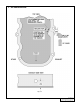
1991-1994 EXPLORER/RANGER Part No. 4FD218-050SQ ® PARTS LIST ENGINEERING, LLC IMPORTANT: Before beginning installation, verify that all parts are included in the kit. Report any shortages or damaged parts immediately.
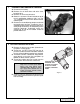
1. PREPARATION/COMPONENT REMOVAL A. Disconnect the battery. B. Remove the air intake duct and valve cover breather hose. C. Remove the accessory drive belt. D. Rotate the vacuum reservoir located on top of the air conditioning condenser 180° (see Fig. 1-a), rerouting the vacuum line attached to the mounting tab. E. Remove the air conditioning compressor, but do not break open any lines. Disconnect the air conditioning line bracket located in front of the water pump.
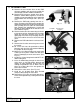
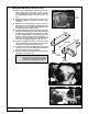
3. OIL DRAIN FITTING A. Remove the two vacuum lines on the EGR reference module and mark their position for reinstallation. Remove module and bracket. B. Remove EGR reference module from mount. Bend the mount down lengthwise so that the module will run perpendicular to the ground to accommodate the discharge tube. (See Fig. 3-a.) C. Remove the EGR tube coming from the exhaust. Disconnect the EGR guard, vacuum line and electrical connector.
3. OIL DRAIN GRAPHIC Fig. 3-e 3 P/N: 4FD020-010 ©2001 Vortech Engineering, LLC All Rights Reserved, Intl. Copr. Secured 31JUL01 V1.1(Explorer/Ranger(4FD V1.
4. MOUNTING BRACKET INSTALLATION A. With the air conditioning compressor temporarily moved off to one side, install the two Vortech supplied 11mm dowel sleeves into the air conditioning compressor mount. (See Fig. 4-a.) B. Position the spacer and bracket on the air conditioning compressor mount as shown. (See Fig. 4-b.) C. Remove the factory dowel sleeves from the bottom of the air conditioning compressor and set aside. Install the compressor on top of the air conditioning mount and brackets. D.
FMU INSTALLATION A. Locate the return fuel line spring lock connector (left side frame below master cylinder). Separate the return line with a spring lock disconnect tool. Snap the Vortech fuel line with the male spring lock connector into the fuel rail outlet. Attach the other end to the Vortech fuel management unit inlet. B. Snap the second line with the female spring lock connector onto the fuel return line that returns to the tank (see Fig. 5-a.
6. FUEL PUMP A. Release any pressure from the fuel tank by momentarily loosening the filler cap. B. Disconnect the line to the fuel filter by carefully removing the white retaining tab. Attach the line to the adapter fitting as shown. C. Mount the fuel pump on the frame near the filter using the supplied #10 nut and bolt. D. Connect the fuel pump inlet to the adapter with the 3/8" hose provided. E. Connect the fuel pump outlet to the filter inlet with the 5/16" hose.
7. SUPERCHARGER INSTALLATION A. Reinstall the EGR valve by connecting the exhaust manifold tube first, then the valve. Tighten all the fittings, EGR bolts and connect all the vacuum lines. B. Reinstall the modified EGR guard. Reconnect all wires and vacuum lines. C. Mount the modified EGR reference module. Reconnect all wires and hoses. D. Mount the supercharger mounting brace from the back of the mounting plate to the cylinder head using the supplied 10mm x 1.
9. AIR INLET DUCT A. Rotate the vacuum tree located on the rear left side of the intake manifold approximately 180° to gain clearance for the intake/discharge plenum. (See Fig. 9-c.) B. On automatic transmission equipped applications, the transmission vacuum line must be removed from the manifold, rerouted and formed to run along the firewall for plenum clearance.
10. SUPERCHARGER DISCHARGE DUCT A. Slide a 2-3/4" x 2" sleeve and two #44 clamps onto the supercharger discharge. Use a 2-1/2" x 2" sleeve with #40 clamps on the discharge plenum. Install discharge tube A. Refer to Fig. 10-a on page 10. B. Mount discharge tubes B and C together using a 2-1/2" x 2" sleeve and #40 clamps. Slide a 23/4" sleeve onto the throttle body and a 2-1/2" sleeve onto the discharge plenum. Attach the discharge tube assembly to the plenum and throttle body using #40 and #44 clamps. C.
10. SUPERCHARGER DISCHARGE DUCT 3" x 3" SLEEVE PLASTIC INTAKE DUCT DISCHARGE TUBE 'A' INTAKE TUBE 'B' 2-3/4" x 2" SLEEVE 2-1/2" x 2" SLEEVE 2-3/4" x 2" SLEEVE FRONT OF VEHICLE 2-1/2" x 2" SLEEVE DISCHARGE TUBE 'C' 2-1/2" x 2" SLEEVE INTAKE TUBE 'A' DISCHARGE TUBE 'B' VALVE COVER BREATHER HOSE BARB RUBBER ELBOW MAF SENSOR Fig. 10-a P/N: 4FD020-010 ©2001 Vortech Engineering, LLC All Rights Reserved, Intl. Copr. Secured 31JUL01 V1.1(Explorer/Ranger(4FD V1.
11. FINAL REASSEMBLY & CHECK A. Reconnect the battery. B. Check all fittings, nuts, bolts and clamps for tightness. Pay particular attention to oil and fuel lines around moving parts, sharp edges and exhaust system parts. Make sure all wires and lines are properly secured with clamps or tie wraps. C. Check all fluid levels, making sure that your tank(s) is filled with 92 octane or higher fuel before commencing test drive. D. Start engine and allow to idle a few minutes, then shut off. E.
® ENGINEERING, LLC 1650 PACIFIC AVENUE • CHANNEL ISLANDS, CA 93033-9901 • (805) 247-0226 FAX (805) 247-0669 • www.vortechsuperchargers.com • M-F 8:00 AM - 4:30 PM PST P/N: 4FD020-010 ©2001 Vortech Engineering, LLC All Rights Reserved, Intl. Copr. Secured 31JUL01 V1.1(Explorer/Ranger(4FD V1.