
user manual

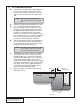
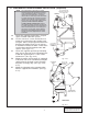
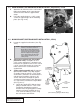


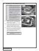


Table Of Contents
- FOREWORD
- TABLE OF CONTENTS
- TOOL AND SUPPLY REQUIREMENTS
- PARTS LIST (Universal Small...
- PARTS LIST (Universal Small...
- PARTS LIST (Universal Small...
- 1. PREPARATION/REMOVAL
- 2. OIL FEED INSTALLATION
- 3. OIL DRAIN INSTALLATION
- 4.1 MAIN BRACKET/SUPERCHARGE...
- 4.2 MAIN BRACKET/SUPERCHARGE...
- 5. CRANK PULLEY AND SUPERCHA...
- 7. FINAL REASSEMBLY AND CHECK
- 6. DISCHARGE DUCTING/CARBURE...
- 7. FINAL REASSEMBLY AND CHECK
P/N: 4GP020-015
©2006 Vortech Engineering, LLC
All Rights Reserved, Intl. Copr. Secured
30MAY06 SmallBlockChev(4GP..015v1.1)
5
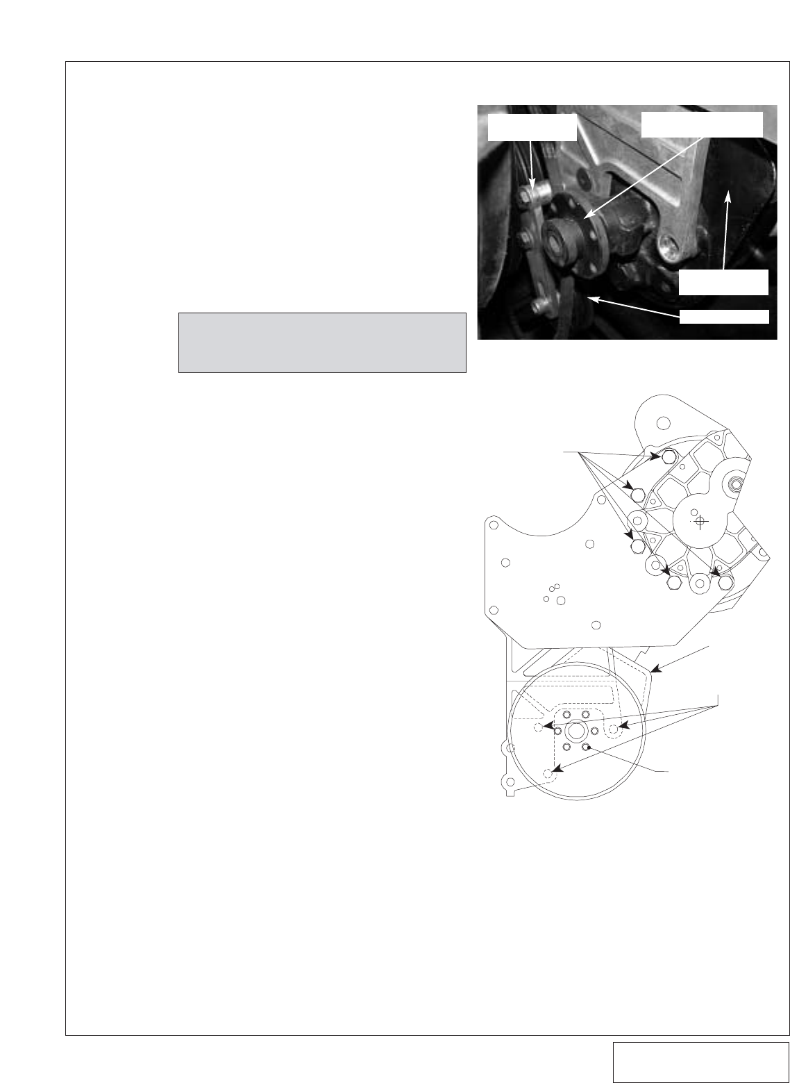
Fig. 4.2-c
NOTE: The end of the pump shaft
should be flush with the end of
the drive flange when fully
installed.
2. Mount the power steering pump to the
back side of the cast bracket using the
supplied 3/8-16 flat-head screws. Locate
the power steering pump drive flange.
Using the appropriate GM power steering
pulley installer, install the drive flange as
you would a normal power steering pulley.
(See Fig. 4.2-b.)
3. Using the six 1/4-20 x .75" screws and
washers, attach the supplied power steer-
ing pulley. (Blue loc-tite on the threads is
recommended.) (See Figs. 4.2-b, 4.2-c.)
FRONT VIEW
3/8-16 FLAT-HEAD
SCREWS
P/S PUMP
SIX 1/4-20 x .75"
SCREWS
AND WASHERS
(V-BELT ONLY)
3/8-16 x
1.0" SCREWS
Fig. 4.2-b
(Power Steering Equipped Models Only)
POWER STEERING
TENSIONER
POWER STEERING PUMP
DRIVE FLANGE
POWER STEERING
PUMP
TENSIONER IDLER
D. Locate the supplied supercharger mounting
plate. Secure the plate to the mounting brack-
et with the supplied 3/8-16 x 1.25" screws
and washers. (See Fig. 4.1-b on previous
page.)
E. Attach the oil drain hose to the 1/2" barbed
fitting on the bottom of the supercharger.
Secure the hose with the supplied hose
clamp.
F. Using the supplied 3/8-16 x 1.0" screws and
washers secure the supercharger to the
mounting plate. (See Fig. 4.2-c.)